Global Site
Displaying present location in the site.
28 GHz Multi-User Massive Distributed-MIMO with Spatial Division Multiplexing
Vol.17 No.1 September 2023 Special Issue on Open Network Technologies — Network Technologies and Advanced Solutions at the Heart of an Open and Green Society PDF
PDFThis paper describes the experimental verifications of a 28 GHz multi-user massive distributed multiple-input multiple-output (MIMO) using comprehensive calibration without an additional transceiver path. A conventional massive collocated-MIMO using millimeter wave has low robustness in non-line of sight environments and restricts the number of simultaneously connected users due to the lack of propagation independent. The newly developed distributed MIMO system consists of the eight distributed active antennas connected to a digital and mixed signal processing unit. The proposed calibration for the distributed MIMO improves the pre-coding accuracy and enhances the number of simultaneously connected users and cell throughput. We demonstrate zero-forcing spatial multiplexing using up-link to down-link channel reciprocity for two, four, and six user equipment in an actual over-the-air office environment. The distributed MIMO shows high robustness in non-line of sight environments and a system throughput of 2.1 Gbps per 100 MHz for the sum of six simultaneous users.
1. Introduction
The beyond 5th and 6th generation mobile access services eager spatial division multiplexing (SDM) technologies by using massive multiple-input multiple-output (MIMO) systems to increase cell throughput and the number of simultaneously connected users. Furthermore, the benefits of using millimeter wave is cell throughput enhancement due to the wide available frequency range. The massive MIMO has two beam forming methods, which are analog and digital beam forming. Although analog beam forming can realize a few analog-to-digital converters (ADCs) and digital-to-analog converters (DACs), it restricts the number of accesses and cell throughput due to without null forming. In contrast, digital beam forming controls amplitude and phase of signals digitally, and enhances cell throughput by using null forming. However, digital beam forming using millimeter wave is constrained by various barriers, such as a limited number of effective multipath due to straightness, shadowing, and loss in propagations.
A collocated MIMO (C-MIMO) system is one of the implementation technique in massive MIMO, which lines up multiple antenna elements with about half wave length spacing in a system. In contrast, a distributed MIMO (D-MIMO) technique ensures the individual effective multipath to maximize the performance of SDM by geometrically distant multiple number of antennas1)–4).
This paper describes the design and implementation of a 28 GHz D-MIMO radio unit (RU) and a newly developed comprehensive calibration over the distributed antennas, and demonstrates the up-link (UL) to down-link (DL) channel reciprocity with simultaneous multiple user connections in over the air (OTA) measurements.
2. 28 GHz D-MIMO Testbed
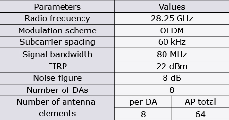
We developed a 28 GHz D-MIMO testbed that consists of a UL and DL mixed signal processing (MSP) unit and eight distributed antenna (DA) units. Fig. 1 shows the block diagram of the AP D-MIMO testbed. Table shows its specifications.
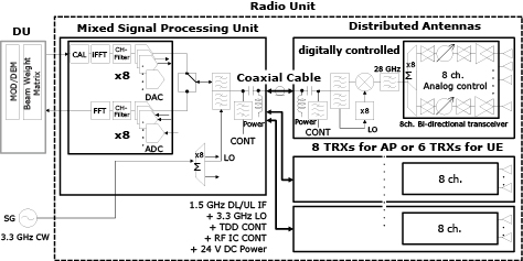
Table Specifications of the D-MIMO testbed.
MSP has a field-programmable array of Xilinx ZU29DR integrated with eight ADCs and eight DACs. The DACs directly generate TX intermediate frequency (IF) signals, and the ADCs directly receives RX IF signals. MSP and DAs have newly de-signed sextuple multiplexers, which multiple a TX IF signal, a RX IF signal, a 3.3 GHz local oscillator (LO) signal, a time division duplex control signal, a radio frequency (RF) integrated circuit (IC) control signal, and 24 V direct current power. The frequency of TX and RX IF signals is 1.5 GHz to decrease cable losses. Thus, each DA can be connected to MSP with a 20 m single coaxial cable and is located to an arbitrary place within the cable length.
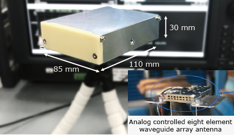
DA has an 8-element waveguide array antenna with a half wave length element spacing at 28 GHz as shown in Fig. 2. The eight antenna elements connect to the eight channel bi-directional transceiver IC based on 65 nm CMOS integrating gain and phase shifters5). DA converts between the IF signals and 28.25 GHz RF signals by mixing with a LO signal generated by eight times of the original 3.3 GHz signal. The effective isotropic radiated power (EIRP) of the DA TX signal is 22 dBm.
A distributed unit (DU) generates digital baseband signals pre-coded with DL beam weights. The DL and UL signals are modulated with orthogonal frequency division multiplexing (OFDM), whose numerology is based on the specifications of 3GPP TS 36.211 format6) except for sub-carrier spacing and signal bandwidth.
3. Calibration for D-MIMO
Transceivers in a conventional MIMO such as C-MIMO are calibrated so that the phase and amplitude are absolutely the same between the all transceivers. The calibration is called absolute calibration. For the absolute calibration, the conventional MIMO has a built-in calibration path to observe RF signals7), and performs the absolute calibration in factory and on-site.
In contrast, the D-MIMO system does not perform the absolute calibration because the calibration path cannot be built in the RU due to the separated DAs. Furthermore, factory calibration is not sufficient enough for the efficient beam forming because the phase and amplitude of D-MIMO signal are varied by the length and forming of the coaxial cable between MSP and DA.
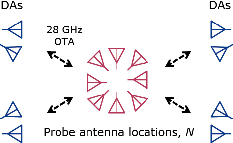
In this work, we propose a new calibration method that can be applicable to D-MIMO and realizes sufficient DL SDM quality. The calibration measures DL and UL calibration signals with OTA transmission by using an external probe antenna as shown in Fig. 3. Calibration signals are based on Zadoff-Chu sequence and are allocated to different subcarriers for each DA to prevent interferences. The calibration signals are measured several times N at different locations and directions of the probe antenna to calibrate the all DAs.
The DL channel coefficient estimated from the calibration measurements between the k-th probe antenna location and the i-th DA, called DA-i, is expressed as follows,

where hk,i is the actual propagation channel from DA-i to the k-th probe antenna, gtx,i is the complex transmitter gain of DA-i, k = 0, 1, …, N, and i = 0, 1, …, 8. Similarly, the UL channel coefficient is expressed as,

where grx,i is the complex receiver gain of DA-i. The calibration parameter for DA-i is calculated as follows,
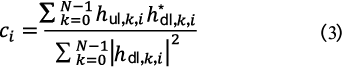
The symbol* denotes complex conjugate. (3) means the weighted average of the gain ratio, grx,i / gtx,i , with the propagation attenuation. The weighted average improves accuracy of the calibration because the contribution of largely attenuated calibration signals, which have large noise, is decreased. The calibration parameter is obtained for each frequency of the subcarrier having the calibration signal, and is multiplied by the TX time-frequency domain OFDM signal.
In this measurement, the probe antenna is allocated to the approximately center of the communication area and is redirected in eight directions, N = 8, as shown in Fig. 3. Although the external probe antenna is used in this measurement, one of DAs can be used as a probe antenna for self-calibration8).
4. Over-the-Air Measurements
Fig. 4 shows the DA and user equipment (UE) locations on an actual office floor. The UEs have the same architecture as the AP D-MIMO system. We evaluate the UL to DL channel reciprocity by changing the number of UEs connected simultaneously and with the same frequency. The number of UEs is two, four, and six, and each UE has single layer transmission.
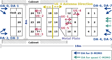
The solid arrows and the dashed arrows show the antenna directions and locations of DAs and UEs, respectively. The directions of UE-0 from Desk-1 to Desk-15 are right, and the others are left.
4.1 Measurement Setup and Procedure
In the measurements, two of the eight DAs are located in each of the four corners in the communication area as shown in Fig. 4. The height of DA is about 1.7 m from the floor.
Up to six UEs, UE-0 to UE-5, are allocated on the desks, and their heights are about 1.7 m from the floor. The UE-0 to UE-1 and the UE-0 to UE-3 are used for two and four UE multiplexing, respectively. The UE-0 is swept from the Desk-1 to Desk-27 to evaluate the multi-user channel reciprocity over the entire measurement area, and the other UEs are fixed to the locations on the desks shown in Fig. 4.
Firstly, AP D-MIMO receives UL signals from UEs and obtains channel coefficients. Subsequently, pre-coding weights are calculated by zero-forcing (ZF) method using the UL channels coefficients and are multiplied by the DL signals in DU. The DL signals use quadrature phase shift keying. The EVM for each UE is measured from the DL signal received through OTA transmission. The EVM measurement is repeated each time the UE-0 moves from Desk-1 to Desk-27 shown in Fig. 4.
4.2 Measurement Results
Fig. 5 shows the heat maps of DL EVMs with four UEs connected simultaneously. Each cell in the heat map corresponds to the UE-0 location from Desk-1 to Desk-27 and represents the measured EVM for each UE. Although EVM degrades in some locations, EVM is lower than about −20 dB in most locations.
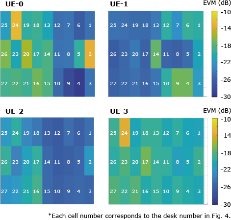
In the previous work, a D-MIMO testbed calibrated at the center frequency only has the EVM of −14 dB with two UEs connection and degrades the EVM according to the signal bandwidth1). EVM of this work is better than that of the previous work because the newly developed calibration can corrects the phase and amplitude frequency dependencies of DAs.
Fig. 6 shows system throughput (STP) as a function of the number of simultaneously connected UEs. STP is the total throughput of all UEs, and is estimated from the measured EVM, assuming the use of 5G New Radio signals with 100 MHz bandwidth9). The circle red and circle blue lines in Fig. 6 show STP of the D-MIMO measurements with and without the metal plate shown in Fig. 4, respectively. STP with the plate is slightly higher than that without the plate, which implies that the signal contamination decreases due to the plate.
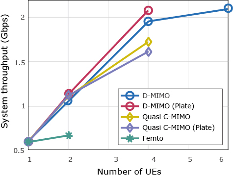
To compare D-MIMO and C-MIMO, STP is measured by the D-MIMO testbed lining up the eight DAs at 3 cm intervals as shown by the green arrows in Fig. 4. Although a general C-MIMO has an antenna spacing of about a half wave length at the radio frequency, DAs cannot be arranged with a half wave length of 28 GHz due to the DA width of 3 cm. Thus, the testbed having these DA locations is called quasi C-MIMO. As shown in Fig. 6, STP of quasi C-MIMO with the metal plate is less than that without the plate due to non-line of sight transmission.
Additionally, we investigate STP for femto-cell base stations. DA is assumed as a femto-cell base station and is connected to a single UE without using SDM in this measurement. UE-0 and UE-1 connect to DA-1 and DA-5, respectively. The green line in Fig. 6 shows STP of femto-cell base stations. STP for two UE connection is almost equivalent to STP for single UE connection due to signal contamination.
5. Conclusion
This paper has presented the experimental investigation of the AP 28 GHz multi-user D-MIMO using newly developed calibration. D-MIMO achieves STP of 2.1 Gbps per 100 MHz with six simultaneous connection and demonstrates higher STP than quasi C-MIMO and the femto-cell base stations. Additionally, the experimental investigation show that D-MIMO has high robustness in non-line of sight environments.
In conventional C-MIMO, the ratio K⁄M = 1⁄4, where the number of UEs is K, and the number of transceivers in the AP is M, is the preferred operating regime for multi-user MIMO7)10). In contrast, the D-MIMO system shows that K⁄M = 1⁄2 is the available regime with sufficient throughput for each UE as shown in Fig. 6.
These findings suggest the potential for improving the cell throughput of the beyond 5th and 6th generation millimeter-wave services in indoor and densely populated outdoor areas with obstacles and pedestrians.
6. Acknowledgement
We would like to thank Professor Kenichi Okada and his laboratory’s researchers at Tokyo Institute of Technology for their core chips prototyping and technical discussion.
References
- 1)
- 2)
- 3)
- 4)S. Kumagai et al.:Experimental Trials of 5G Ultra High-Density Distributed Antenna Systems, 2019 IEEE 90th Vehicular Technology Conference (VTC2019-Fall), pp.1-5, 2019
- 5)
- 6)
- 7)
- 8)
- 9)NR; Physical channels and modulation, version 15.4.0: 3GPP TS 38.214, December 2018
- 10)E. Bjornson, Jakob Hoydis, and Luca Sanguinetti: Massive MIMO Networks: Spectral, Energy, and Hardware Efficiency, Now Publishers, 2017
 N. Tawa, T. Kuwabara, Y. Maruta and T. Kaneko: Measuring Propagation Channel Variations and Reciprocity using 28 GHz Indoor Distributed Multi-user MIMO, 2020 IEEE Radio and Wireless Symposium (RWS formerly RAWCON), pp.104-107, January 2020
Authors’ Profiles
TAWA Noriaki
Professional
Wireless Access Development Department
Professional
Wireless Access Development Department
KUWABARA Toshihide
Senior Professional
Wireless Access Development Department
Senior Professional
Wireless Access Development Department
MARUTA Yasushi
Senior Professional
Wireless Access Development Department
Senior Professional
Wireless Access Development Department
KANEKO Tomoya
Senior Professional
Wireless Access Development Department
Senior Professional
Wireless Access Development Department