Global Site
Displaying present location in the site.
28 GHz Over-the-Air Measurements Using an OTFS Multi-User Distributed MIMO System
Vol.17 No.1 September 2023 Special Issue on Open Network Technologies — Network Technologies and Advanced Solutions at the Heart of an Open and Green Society PDF
PDFThe mainstays to increase cell throughput for the beyond 5G or later are multiple-input multiple-output (MIMO) techniques, the use of millimeter wave and sub-THz, and a modulation scheme. Orthogonal frequency-division multiplexing (OFDM) modulation, which is used for 4G and 5G, has high spectral efficiency and high robustness to multi-path fading channels. In contrast, OFDM has low robustness to time-varying channels for moving terminals, which is more important at millimeter wave and sub-THz transmission than for sub-6 GHz. This paper describes the experimental investigation of orthogonal time frequency space (OTFS) modulation using a 28 GHz multi-user distributed MIMO testbed in over-the-air and mobility environments. We measure OTFS and OFDM up-link signals with up to four user simultaneous connections using zero-forcing precoding. OTFS indicates higher robustness to time-variant channels than OFDM. The error vector magnitude and system throughput of OTFS are −22 dB and 1.9 Gbps with 100 MHz signal bandwidth, respectively. OTFS enables cell throughput enhancement for moving terminals in millimeter wave and sub-THz bands.
1. Introduction
Multiple-input multiple-output (MIMO) techniques, the use of a millimeter wave (mmW) band and a sub-THz band, and a new modulation scheme are the key factors to enhance cell throughput for the beyond 5th generation (B5G) and 6th generation (6G) mobile services. The MIMO system using spatial division multiplexing (SDM) techniques can multiple the larger number of layers than that using direction based beam-forming. The advantage of using mmW and sub-THz is wide available frequency range, whereas the difficulty is that mmW and sub-THz change the propagation channel more sensitively than sub-6 GHz. A modulation scheme having high robustness to the channel sensitivity is required for B5G and 6G. The modulation technique for 4th and 5th generation mobile services is orthogonal frequency-division multiplexing (OFDM). Although OFDM has high spectral efficiency and good robustness to multi-path fading, inter-carrier interference due to the Doppler spread of time-varying channels degrades OFDM performance for mobility environments. Especially, Doppler spread in mmW and sub-THz is larger than that in sub-6 GHz. To suppress the degradation, an OFDM system allocates reference signals (RS) more frequently and calculates SDM weight matrixes for each OFDM symbol. However, increasing RS allocations decreases spectral efficiency and increases computational complexity for weight calculation.
Orthogonal time frequency space (OTFS) is suggested to tackle the time-varying channels1). OFDM multiplexes information symbols in the time-frequency (TF) domain, whereas OTFS multiplexes them in the delay-Doppler (DD) domain. Because the OTFS modulation spreads each element in the DD domain into the TF domain entirely, all OTFS elements experience the same and nearly constant propagation channel. Using simulation, the previous works report that OTFS has a lower bit error rate than OFDM for high mobility environments1)-4).
We investigate the robustness of OTFS modulation in the Doppler environment with over-the-air (OTA) experiments using a 28 GHz multi-user distributed MIMO (D-MIMO) testbed. D-MIMO is one of the technique to maximize the SDM performance by using geometrically distant multiple number of antennas5)-7). This paper describes the practical OTFS channel estimation and channel quality with simultaneous multiple user connections for mobility environments.
2. Signal Processing
2.1 OTFS Modulation
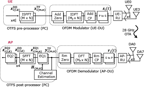
Fig. 1 shows the OTFS signal processing diagram. An OTFS pre-processor on a personal computer (PC) generates a multi-user transmitted (TX) signal ![]() , where U = 1,2,or 4 is the number of user equipment (UEs). The OTFS signal
, where U = 1,2,or 4 is the number of user equipment (UEs). The OTFS signal ![]() is TX information in i-th subframe, where i = 0, 1,…, 9, and is allocated to the DD domain element of a delay domain index l = 0,1,…,9,M-1 and a Doppler domain index k = 0,1,...,N-1, where M and N are 1200 and 14, respectively. An OTFS frame has 10 subframes. The OTFS pre-processor converts
is TX information in i-th subframe, where i = 0, 1,…, 9, and is allocated to the DD domain element of a delay domain index l = 0,1,…,9,M-1 and a Doppler domain index k = 0,1,...,N-1, where M and N are 1200 and 14, respectively. An OTFS frame has 10 subframes. The OTFS pre-processor converts ![]() to a TF domain signal
to a TF domain signal ![]() , where m = 0,1,...,M-1 is a frequency domain index and n = 0,1,...,N-1 is a time domain index, using the inverse symplectic finite Fourier transform (SFFT)1)-4). A distributed unit (DU) for UE, called UE-DU, generates a time domain digital signal
, where m = 0,1,...,M-1 is a frequency domain index and n = 0,1,...,N-1 is a time domain index, using the inverse symplectic finite Fourier transform (SFFT)1)-4). A distributed unit (DU) for UE, called UE-DU, generates a time domain digital signal ![]() , where t is time, by modulating the TF domain signal
, where t is time, by modulating the TF domain signal ![]() with OFDM modulation. The numerology of the OFDM modulation is based on the specifications of 3GPP TS 36.211 format8) except for subcarrier spacing and signal bandwidth, which are 60 kHz and 80 MHz respectively. A radio unit (RU) for UE, called UE-RU, converts the time domain digital signal si(t) to an analogue signal and then radiates it from UE antennas.
with OFDM modulation. The numerology of the OFDM modulation is based on the specifications of 3GPP TS 36.211 format8) except for subcarrier spacing and signal bandwidth, which are 60 kHz and 80 MHz respectively. A radio unit (RU) for UE, called UE-RU, converts the time domain digital signal si(t) to an analogue signal and then radiates it from UE antennas.
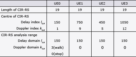
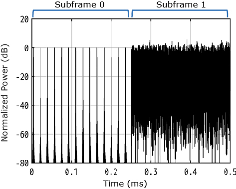
Subframe 0 has only reference signals to estimate a channel impulse response (CIR), which are called CIR-RS. CIR-RS using the root Zadoff-chu sequence with a length of 19 as defined in 3GPP TS 36.2118) is allocated to the DD domain elements as shown in Fig. 2. Table 1 shows delay indexes lc,u and Doppler indexes kc,u for the CIR-RS center locations of four UEs, UE0 to UE3. The other elements in subframe 0 are blank. Subframe 1 to subframe 9 have quadrature phase shift keying (QPSK) TX information and phase compensation reference signals (PCRS). PCRS for the u-th UE is a QPSK sequence and is allocated to ![]() , where lp = 48v+u, v = 0,1,...,24, and u=0,1,2,3, as shown in Fig. 2. The PCRS and CIR-RS locations are different for each UE to prevent contamination between UEs. The amplitude of CIR-RS is 17 dB larger than those of the TX information sequence and PCRS to equalize the peak power of the time domain signal si(t) between subframe 0 and the other subframes as shown in Fig. 3.
, where lp = 48v+u, v = 0,1,...,24, and u=0,1,2,3, as shown in Fig. 2. The PCRS and CIR-RS locations are different for each UE to prevent contamination between UEs. The amplitude of CIR-RS is 17 dB larger than those of the TX information sequence and PCRS to equalize the peak power of the time domain signal si(t) between subframe 0 and the other subframes as shown in Fig. 3.
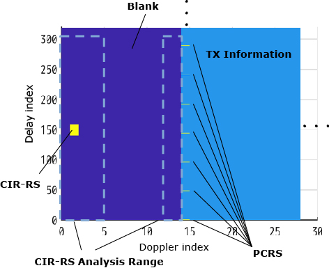
Table 1 Numerology for CIR-RS.
2.2 OTFS Demodulation
An RU for AP, called AP-RU, receives the 28 GHz OTA signal and converts the received signal to the digital baseband signal, ![]() , where D = 8 is the number of distributed antennas (DAs). A DU for access point (AP), called AP-DU, generates a TF domain OTFS signal
, where D = 8 is the number of distributed antennas (DAs). A DU for access point (AP), called AP-DU, generates a TF domain OTFS signal ![]() from the baseband signal ri(t) using OFDM demodulation.
from the baseband signal ri(t) using OFDM demodulation.
The propagation channels are estimated by using subframe 0 having CIR-RS. Firstly, the channel estimator in the OTFS post-processor on a PC converts the TF domain signal ![]() to the DD domain signal
to the DD domain signal ![]() using SFFT, and then extracts CIR-RS from
using SFFT, and then extracts CIR-RS from ![]() . The extracted signal for the u-th UE is expressed as
. The extracted signal for the u-th UE is expressed as
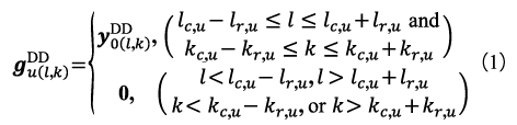
where lr,u and kr,u are the CIR-RS analysis ranges of delay domain and Doppler domain, respectively, as shown in Table 1. The CIR-RS analysis range is larger than the CIR-RS allocation range because CIR-RS is distributed by delay and Doppler effect. When the Doppler indexes of CIR-RS analysis range are over subframe 0, the indexes are folded in subframe 0 as shown in Fig. 2. The channel estimator converts the extracted signal ![]() to the TF domain signal
to the TF domain signal ![]() with inverse SFFT and calculates the propagation channel of the u-th UE as
with inverse SFFT and calculates the propagation channel of the u-th UE as

where,![]() is the TF domain TX signal of the u-th UE in
is the TF domain TX signal of the u-th UE in ![]() . The channel estimator obtains the channel matrix as H(m,n) = [h0(m,n),h1(m,n),...,hu-1(m,n)] .
. The channel estimator obtains the channel matrix as H(m,n) = [h0(m,n),h1(m,n),...,hu-1(m,n)] .
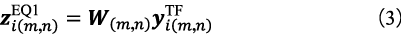
The first equalizer (EQ1) performs channel equalization in the TF domain. The equalized OTFS signal is calculated as
where ![]() is the equalization weight calculated from the channel matrix H(m,n) by ZF. Subsequently, the OTFS post-processor converts the equalized signal
is the equalization weight calculated from the channel matrix H(m,n) by ZF. Subsequently, the OTFS post-processor converts the equalized signal ![]() to the DD domain signal
to the DD domain signal ![]() using SFFT.
using SFFT.
The second equalizer (EQ2) corrects the DD domain signal as follows,

where,

The symbols of ![]() and
and ![]() denote the Hadamard product and division, respectively. The correction parameters
denote the Hadamard product and division, respectively. The correction parameters ![]() in the delay indexes without PCRS are linearly interpolated from the adjacent correction parameters in
in the delay indexes without PCRS are linearly interpolated from the adjacent correction parameters in ![]() .
.
3. Over-the-Air Measurements
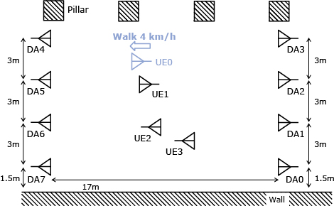
The newly developed 28 GHz D-MIMO testbeds7) are used for UE-RU and AP-RU. The D-MIMO testbed for UE-RU has four DAs, and that for AP-RU has eight DAs. Each DA of UE-RU is used as a UE. The DA is connected to a mixed signal processing unit by a single 20 m coaxial cable and thus can be located at arbitrary place within the cable length.
Fig. 4 shows the experimental layout of eight DAs, DA0 to DA7, and four UEs, UE0 to UE3, on an office floor. The heights of DAs and UEs are about 1.7 m from the floor. UEs are located in the line of sight of any of DAs. UE0 is used for single user measurements, and UE0 and UE1 are used for two user multiplexing. Our measurements have two parts as follows. In the part-1, UE0 moves to left direction in Fig. 4 at walking speed, whereas the other UEs are fixed at the initial locations. Because CIR-RS is spread in Doppler domain for mobility environments, the CIR-RS analysis range of Doppler domain for UE0, kr,u=0 , is three as shown in Table 1. The CIR-RS analysis ranges kr,u for the other UEs are zero to decrease additive white Gaussian noise contaminated to the channel estimation. In the part-2, all UEs are fixed at the initial locations, and their CIR-RS analysis ranges kr,u are zero.
4. Measurement Results
Fig. 5 shows the UE0 OTFS constellations in the part-1 measurements. Although the constellation without using EQ2 shown in Fig. 5(a) is rotated for each subframe by Doppler frequency shift, the rotation is corrected by EQ2 as shown in Fig. 5(b).
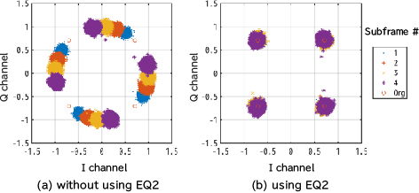
Fig. 6 shows the measured error vector magnitudes (EVMs) as a function of the number of simultaneously connected UEs. AP D-MIMO can demodulate the multi-user OTFS signals, which are emitted in the same frequency band and the same time, using ZF in the actual OTA and Doppler environments.
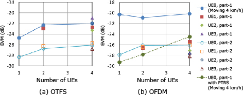
In the part-2 measurements, which all UEs are fixed, the OTFS EVMs are about the same as the OFDM EVMs regardless of the number of connected UEs. In contrast, the EVMs of the moving OTFS UE0 in the part-1 measurements are several dB less than those of the moving OFDM UE0, which is shown by the solid circles in Fig. 6. The circle dashed line in Fig. 6(b) shows the EVMs of the moving OFDM UE0 using phase tracking reference signals (PTRS).
PTRS is based on the specifications in 3GPP TS 38.2119), which is allocated for each 48 subcarriers intervals in fourth to 14th OFDM symbols for each subframe. The OFDM EVMs of UE1 to UE3 with PTRS are about the same as those without PTRS because these UEs are fixed. Although the moving OFDM UE0 with PTRS has less EVM than the moving OTFS UE0, computational complexity for equalizations increases to use PTRS. The OTFS demodulator calculates the equalization weights for each 10 subframes, whereas the OFDM demodulator using PTRS calculates the weights for each subframe. Thus, the computational complexity to obtain the equalization weights of OFDM using PTRS is 10 times greater than that of OTFS.
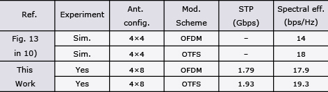
Table 2 shows comparison with the previously reported OTFS and OFDM systems without using PTRS. The system throughput (STP) and spectral efficiency of this work are estimated from the UE0 EVMs in the part-1 measurements by using MATLAB 5G toolbox. The STP is sum of four user throughputs with 100 MHz bandwidth signals. The experimentally estimated spectral efficiencies of this work are compatible with those of the previous work10) calculated by simulation.
Table 2 Comparison with the previously reported OTFS system.
5. Conclusion
This paper has presented experimental investigation of OTFS performances using our newly developed 28 GHz D-MIMO testbed in OTA and mobility environments. We have measured EVM with up to four user simultaneous connections in the actual office room. OTFS has better EVM and higher spectral efficiency than OFDM without PTRS for moving UE and achieves higher robustness to time-variant channels. These findings suggest that OTFS is one of the key technology to realize the B5G and 6G mobile communication systems used for high mobility environments and in high frequency range such as mmW and sub-THz.
6. Acknowledgement
This research is partially supported by the Ministry of Internal Affairs and Communications in Japan (JPJ000254).
References
- 1)
- 2)
- 3)
- 4)
- 5)
- 6)
- 7)
- 8)Evolved Universal Terrestrial Radio Access (E-UTRA); Physical channels and modulation, version 10.7.0: 3GPP TS 36.211, February 2013
- 9)NR; Physical channels and modulation, version 15.8.0: 3GPP TS 38.211, December 2019
- 10)
 R. Hadani et al.: Orthogonal Time Frequency Space Modulation, 2017 IEEE Wireless Communications and Networking Conference (WCNC), pp.1-6, March 2017
Authors’ Profiles
TAWA Noriaki
Professional
Wireless Access Development Department
Professional
Wireless Access Development Department
KUWABARA Toshihide
Senior Professional
Wireless Access Development Department
Senior Professional
Wireless Access Development Department
MARUTA Yasushi
Senior Professional
Wireless Access Development Department
Senior Professional
Wireless Access Development Department
KANEKO Tomoya
Senior Professional
Wireless Access Development Department
Senior Professional
Wireless Access Development Department