Global Site
Displaying present location in the site.
NEC’s Network Slicing Supports People’s Lives in the 5G Era
Vol.17 No.1 September 2023 Special Issue on Open Network Technologies — Network Technologies and Advanced Solutions at the Heart of an Open and Green Society PDF
PDF5G (fifth-generation mobile communication system) defines network slicing technology that virtually separates the network layers. Network slicing makes it possible to provide use cases required for 5G — such as high speed and high capacity (eMBB), multiple connections (mMTC), and ultra-reliability and low latency (URLLC) — on a single network infrastructure. 5G is expected to solve a variety of social issues, and this paper introduces the network slicing technology developed by NEC that enables communications service providers to provide services promptly.
1. Introduction
Faced with social issues such as a declining birthrate, an aging population, and depopulation, Japan is reaching the limits of its traditional reliance on people to deal with these issues. The use of ICT is indispensable to solve social issues such as the decrease in the workforce and public services, the continuation of store operations, and the maintenance of functions required for daily life and economic activities. 5G, characterized by its ability to communicate large volumes of data with various devices at low latency, is expected not only to solve these problems as a means of digital transformation (DX)*1 in society as a whole but also to serve as the foundation for a more affluent lifestyle. This paper introduces the network slicing of NEC as a technology that can be used to solve these social issues.
- *1Changing the shape or style of business, society, and life through digital technology.
2. Network Slicing Technology
2.1 Features of 5G networks and application of slicing technology
Since their introduction in the 1980’s, mobile communications systems have evolved over the course of each decade and are presently so widespread globally that the number of cellphone subscribers has exceeded the number of people. Nevertheless, mobile communication systems shared limited radio resources until4G, and mobile communications providers had to provide services using best-effort networks.
5G networks have three main features: 1) high speed and high capacity; 2) multiple connections; as well as 3) ultra reliability and low latency. These features are expected to be applied not only to cellphones but also to industrial domains. For example, high speed and high-capacity communications for use cases such as high-definition video distribution and VR*2/AR*3, multiple connections for use cases such as logistics management and smart cities, and ultra reliability and low latency for applications such as remote control and autonomous driving are requirements for networks (Table).
Table Features of 5G and examples of use cases.
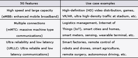
To achieve all this, 5G requires networks that can respond to a variety of requirements. But building individual networks for each requirement is not realistic because it leads to excessive plant investment and operational burdens. In addition, 5G, which is expected to be a means of digital transformation, requires a flexible network that can quickly follow up on changes to help solve whatever social issues emerge in the future.
In 5G, a technology called network slicing has been introduced to form virtual logical networks (slices) on the physical network. Network slicing can separate traffic for different applications and services with different requirements. For example, one service can be provided in a high-speed, high-capacity slice while another service can be provided in a highly reliable, low-latency slice.
- *2Virtual reality: Technology that enables the user to simulate a seemingly real virtual space created by digital technology.
- *3Augmented reality: Technology that virtually enhances or augments an existing landscape by superimposing virtual visual information on it.
2.2 Overview of network slicing architecture
Network slicing logically divides configurations and resources according to the requirements of a service. 5G introduces this technology in core networks and radio access networks (Fig. 1).
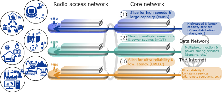
The standard technical specifications for network slicing were established in the 3rd Generation Partnership Project (3GPP) Release 15. A slice identifier called single network slice selection assistance information (S-NSSAI) is defined as signaling information, and slices are formed by notifying the S-NSSAI from the terminal to the radio access network (RAN) and core network. The S-NSSAI also includes the following service types: high speed and high capacity (eMBB), multiple connections (mMTC), as well as ultra reliability and low latency (URLLC).
2.3 Network slicing in the core network
The basic configuration of a 5G core network (5GC) is defined by 3GPP. The system configuration depends on the mobile communications providers and vendors, but in any configuration, the UPF*4 is deployed on a slice-by-slice basis (Fig. 2).
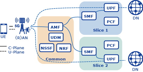
The 5G terminal (UE) uses the call processing signal (on the C-plane) to send the slice identifier (S-NSSAI) to the AMF*5 when communication starts. The AMF selects the SMF*6 according to the slice identifier requested by the terminal, and then the SMF selects the UPF to form a slice in the core network.
The UPF is a function in the core network that enforces quality of service (QoS) rules for user packets (on the U-plane) and transmits or receives user packets to and from the data network (DN). Assigning a UPF to every slice guarantees the QoS of user packets required by each slice.
Because 5GC accommodates networks with different features and is a social infrastructure system, the QoS of each slice is an important requirement.
- *4User plane function: Function for processing user data that is transmitted or received.
- *5Access and mobility management function.
- *6Session management function.
3. Realization of Network Slicing
3.1 Issues in realizing network slicing
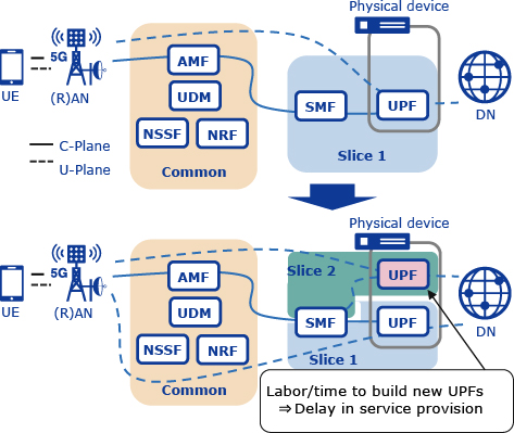
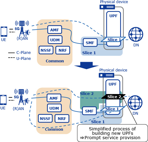
Terminals can select a slice for use in data communications according to the application and service type. However, because the application is not aware of the slice, user packets do not contain information for identifying the slices. Consequently, as described in section 2.3, the UPF must be deployed for each slice to process user packets on a slice-by-slice basis. If slices are built on a per-service basis, the UPF must be built every time a service is added. In such cases, it is necessary not only to build the UPF but also to add settings to the peripheral network devices (for example, the UPF IP address to the SMF, slice information, etc.). This means that the prompt, responsive provision of services required for digital transformation cannot be attained (Fig. 3).
If the UPF can accommodate several slices, mobile communications providers can provide services by simply adding new slices to the UPF that has already been built. This can simplify the work involved in adding services and thus speed up the process of providing services (Fig. 4). To make this possible, the physical resources (e.g., CPU cores) of a UPF must be separated by slices, and packets must be processed independently for each slice in the UPF.
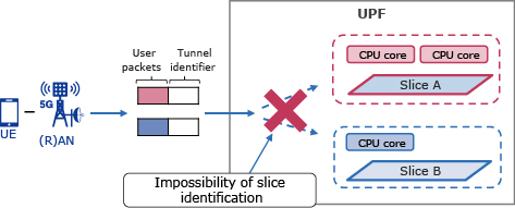
However, the UPF cannot identify slices from user packets. When user packets from multiple slices are mixed together when received, the UPF cannot process the user packets by separating them by slice (Fig. 5).
3.2 NEC’s network slicing technology
A tunneling protocol called General Packet Radio Service Tunneling Protocol (GTP)*7 is used between the base station (RAN) and the UPF. In the tunnels, user packets are encapsulated into a GTP packet (a GTP header is added to each of the user packets) and then sent and received. The GTP header contains a tunnel identifier*8 that is unique to each terminal and assigned by the UPF when the terminal connects to the core network.
The NEC UPF uses a tunnel protocol called the Generic Routing Encapsulation (GRE) for forming the slices between the UPF and the DN. In the tunnels, user packets are encapsulated into a GRE packet and then sent and received. The GRE header also contains a tunnel identifier that is unique to each terminal and assigned by the UPF.
To solve the challenges described in section 3.1, the NEC UPF enables the user packet slice to be identified by implementing the following functionality (Japanese unexamined patent publication no. 2021-170729).
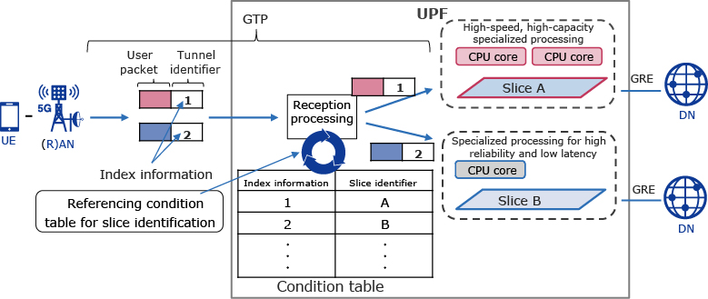
- (1)Assignment of index information to tunnel identifiers
The UPF assigns index information (a value associated with the S-NSSAI to identify a slice) when assigning GTP or GRE tunnel identifiers. - (2)Construction of a condition table for slice identification
The UPF constructs a table that maps index information to the S-NSSAI. - (3)Matching of index information with the condition table
When a user packet is received, the UPF identifies the slice by referencing the index information contained in the tunnel identifier and matching it against the condition table (Fig. 6).
When slice-specific processing is performed in the UPF, the reception processing of the UPF needs to simultaneously process user packets in multiple slices. Because this causes the load to be concentrated in the reception processing, the overall system performance may be affected if the UPF is implemented only as software. The NEC UPF separates the slice identification processing from the CPU and utilizes a SmartNIC*9 to execute the processing with the network interface card (NIC). By identifying the slice on the SmartNIC, simultaneous processing of user packets in more than one slice is possible while the impact on performance is minimized.
This technology makes it possible to separate resources in the UPF for each slice and independently perform processing with different characteristics in accordance with the requirements of the slice in a single UPF. For example, a high-speed, high-capacity slice performs processing specialized for achieving a high bandwidth while a high-reliability, low-latency slice performs processing specialized for guaranteeing real-time performance.
This eliminates the need to construct a new UPF when a new service is necessary, so new services can be provided promptly by simply adding a slice to an existing UPF. NEC expects that this technology can quickly provide the networks required by users in the 5G era to solve social issues and that this technology will be used in various cases in the future.
- *7A communication protocol for constructing virtual transmission paths on a network and sending or receiving data.
- *8Tunneling Endpoint Identifier (TEID) that can be set by the UPF with an arbitrary value for each user packet.
- *9An NIC that can reduce the CPU load by using a special processor (e.g., a field-programmable gate array (FPGA)) to execute CPU processing on the NIC for IP user packet processing and other load-bearing processes that cause the processing capacity to drop.
4. Conclusion
In this paper, we describe NEC’s network slicing technology designed to solve various social issues. NEC is determined to promote activities that emphasize collaboration with customers, to demonstrate the superiority of NEC’S network slicing, and to realize its implementation in society.
5. Acknowledgement
The achievements reported herein are based on results obtained from the “Research and Development Project of Enhanced Infrastructures for Post-5G Information and Communication Systems” (JPNP20017) commissioned by the New Energy and Industrial Technology Development Organization (NEDO).
Authors’ Profiles
TAYAMA Youji
Assistant Manager
Mobile Core Department
Assistant Manager
Mobile Core Department
AOYAGI Masato
Professional
Network Support Services Department
Professional
Network Support Services Department
SAKUTA Sadayuki
Professional
Mobile Core Department
Professional
Mobile Core Department
ISHIKURA Satoshi
Assistant Manager
Telecom Carrier Software Development Department
Assistant Manager
Telecom Carrier Software Development Department
NAGATOMO Kengo
Assistant Manager
Mobile Core Department
Assistant Manager
Mobile Core Department