Global Site
Displaying present location in the site.
39 GHz 256 Element Hybrid Beam-formingMassive MIMO for 8 Multi-users Multiplexing
Vol.17 No.1 September 2023 Special Issue on Open Network Technologies — Network Technologies and Advanced Solutions at the Heart of an Open and Green Society PDF
PDFWhile large-scale multiple-input, multiple-output (Massive MIMO) system base stations have already been commercially deployed in the Sub6 GHz band in 5G (fifth-generation mobile communication system), similar deployments are expected in millimeter-wave base stations to support higher traffic capacity.
This paper describes the design and implementation of a 39 GHz 256-element hybrid active phased array antenna system with 16 individual digital transceivers and its wireless multi-user, multi-input, multi-output verification. The prototype is realized using a beamforming IC for 39 GHz antenna arrays based on a 65 nm CMOS process developed in collaboration with Tokyo Institute of Technology. Furthermore, a compact, high-density mounting method was studied, and a new 256-element array antenna module was developed by employing waveguide antennas to fully exploit millimeter-wave performance. Using the prototype, we conducted a multi-user MIMO (MU-MIMO) transmission test using zero-forced orthogonal multi-beam based on channel interoperability assuming an access link. As a result, an estimated total throughput of 2.42 Gbps according to 3GPP TS38.214 was achieved in 100 MHz band OFDM 8 MU-MIMO operation.
1. Introduction
Spatial division multiplexing (SDM) based on coherent beamforming using large-scale multiple-input multiple-output (Massive MIMO) system base stations is already commercially deployed and is common in 5G (fifth-generation mobile communication system) in systems using the Sub6 GHz band1)2). On the other hand, in millimeter-wave, base stations typically use analog beamforming. However, with the proliferation of millimeter-wave mobile access systems, OFDM orthogonal multi-beam capability for multi-user MIMO (MU-MIMO) access links is expected to be needed in millimeter-wave to support higher capacity traffic.
Achieving spatial multiplexing with MU-MIMO requires zero-force (ZF) coherent beamforming techniques. Analog beamforming is a technique to adaptively increase the directivity of antennas to counter the high propagation loss in millimeter-waves, so to speak, to “deliver the radio wave to the terminal,” whereas ZF coherent beamforming is a technique to “keep the radio wave from reaching the terminal,” thus suppressing interference.
Thus, if the composite gain of the array antenna can be optimally controlled to cancel out unwanted radio waves for each terminal, it is possible to connect to many terminals simultaneously without interference, and this seems to be possible in millimeter-wave. However, the higher the frequency, the more difficult it becomes to ensure the performance of the device, and the more difficult it becomes to implement the device to extract that performance. Considering these factors, there is an urgent need to confirm the performance of space division multiplexing at millimeter-waves through demonstration experiments involving the entire device.
This paper describes the design and implementation of an active phased array antenna system with 256 antenna elements for hybrid beamforming in the 39 GHz band and the verification of MU-MIMO for mobile access applications. An earlier version of this paper was presented at the 51st European Microwave Conference (EuMC) in 2021 and published in its Proceedings3). The validation of MU-MIMO uses reciprocity-based ZF coherent beamforming to verify multiplexing tests for up to 8 users.
2. Design and Structures
Fig. 1 shows a block diagram of the advanced antenna systems (AAS) consisting of baseband (BB) and intermediate frequency (IF) processing units, 16 radio frequency (RF) converter units, and 16 antenna units.
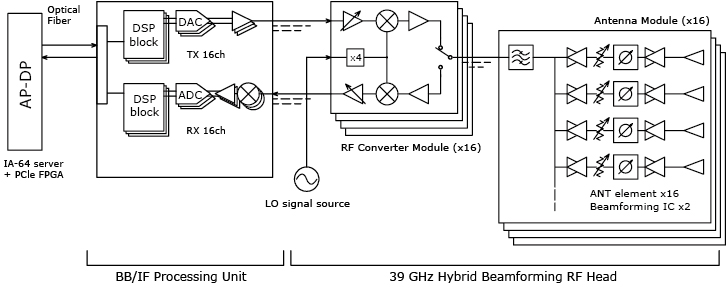
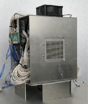
Photo 1 is a photograph of a prototype AAS with the RF converter unit and antenna units integrated into the subsystem housing described in Fig. 1. Excluding the fan unit, it occupies approximately 200 mm in width, 200 mm in depth, and 250 mm in height. The converter unit and antenna unit are connected to the BB/IF processing unit by 16 transmit IF signal and 16 receive IF signal cables.
The BB/IF processing unit is FPGA-based and includes a 16-channel digital signal processing section, an AD/DA data converter, and an IF signal processing section. The digital signal processing section generates 16-channels of MIMO pre-coded baseband signals.
The analog signal input/output of the BB/IF processing unit is performed by IF signals, each of which is connected to a converter unit for conversion to 39 GHz signals. An antenna unit is further connected to the converter unit.
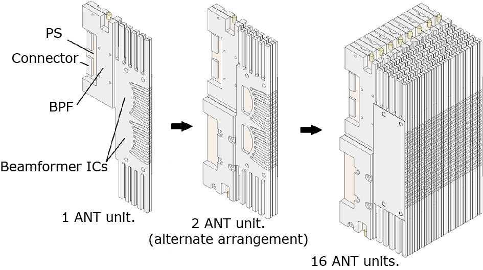
Photo 2 shows one of the antenna units in the AAS. This antenna unit contains two 8-channel transmit/receive analog beamforming ICs using 65 nm CMOS. These ICs were prototyped as a frequency-extended version of the previously announced 28 GHz IC, which was the result of joint research with Tokyo Institute of Technology4). One of the features of this IC is that it shares a phase shifter between transmitter and receiver, and also uses a bidirectional circuit in the amplifier section, resulting in a configuration with excellent reciprocity between transmitter and receiver. Ensuring reciprocity is an important factor in achieving zero-force (ZF) coherent beamforming.
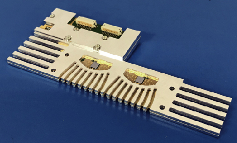
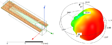
The antenna element is a waveguide structure and is connected to the beamforming IC by a microstrip line. The conversion between the microstrip and waveguide is performed by a tapered fin line constructed on a printed circuit board. The microstrip lines connecting the beamforming IC to the waveguide are arranged to be as short as possible, and the feed to the antenna is done by the waveguide. This structure is effective in reducing the feed loss of the antenna. The waveguide structure consists of a dielectric substrate sandwiched in the cross-section, which allows for a smaller waveguide size. Generally, waveguides are avoided for mounting in equipment because of their large size, but in this case, the cross-section is only about 4 mm wide and 2 mm height, making it small enough to configure an array antenna. Fig. 2 shows the simulated radiation pattern of a single antenna element; 16 waveguide antenna elements are arranged in one antenna unit.
The 16 antenna units are stacked to form an antenna module with 256 elements. As shown in Fig. 3, the arrangement of tall components such as a bandpass filter (BPF) and power supply (PS) circuits in the antenna unit is separated from the arrangement of antennas and ICs to achieve a shape that allows the antenna units to be stacked alternately5). As a result, the spacing between antenna elements can be aligned at short lengths close to half a wavelength while managing heat dissipation.
3. Measurement Results
To achieve MU-MIMO, all 16 transceivers in the AAS radio unit (RU) must be calibrated6). If calibration is incomplete, it is assumed that not enough null signals will be formed and multiple unwanted layer signals will accumulate, reducing the effectiveness of interference suppression. The experiment was fully calibrated prior to the experiment, and calibration coefficients are prepared for each resource block and each transceiver and applied by the DSP. This enables channel estimation using uplink and downlink reciprocity.
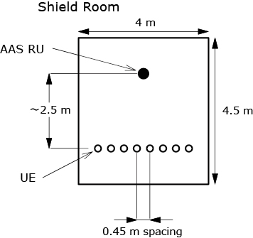
The experiment was conducted in a shielded room, with 8 antennas and converter modules placed opposite the prototype equipment, which were designed to look like user equipment (UE). Their placement is shown in the Fig. 4, and their positions were not changed throughout the experiment.
The test signal used in the experiment was an OFDM signal compliant with 3GPP TS38.214 with a bandwidth of 100 MHz. First, SRS signals were output from several UEs, received by the AAS RU, and analyzed. The beam weights were calculated using this information. Next, MU-MIMO transmission was performed for multiple UEs using the ZF method. The output power was normalized so that the waveform distortion of each antenna output would not change when the number of layers was changed. For signal evaluation, the IF signals obtained from the downconverter of each UE were analyzed with a Keysight vector signal analyzer.
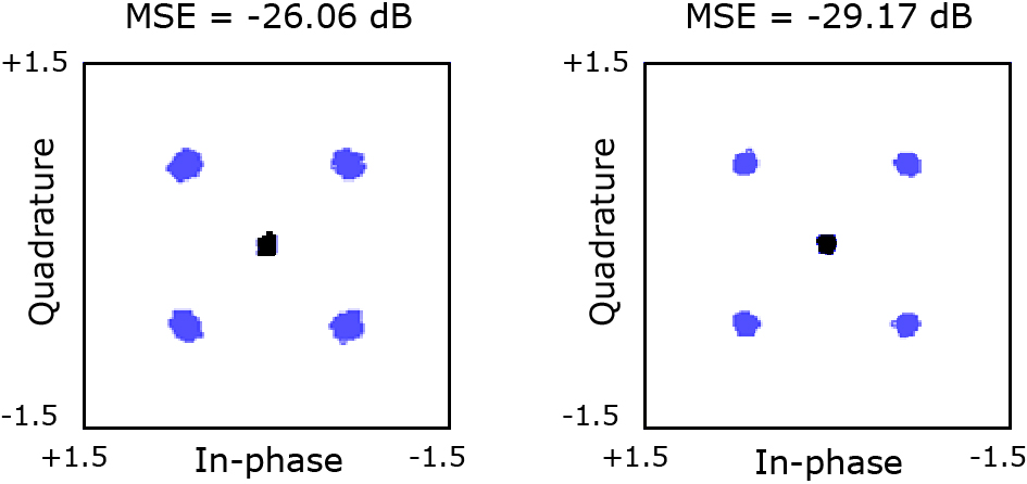
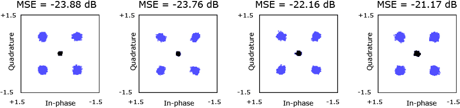
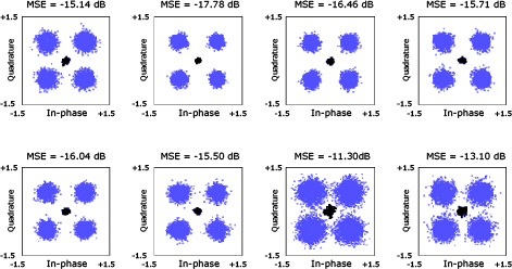
Fig. 5, 6 and 7 show examples of QPSK constellations observed in experiments with 2, 4 and 8 UEs. For the 8 UE experiment, EVM values were -15.14 dB, -17.78 dB, -16.46 dB, -15.71 dB, -16.04 dB, -15.50 dB, -11.30 dB and -13.10 dB. 3GPP TS38.214 Using an OFDM signal with a bandwidth of 100 MHz, the estimated total throughput using rank adaptation according to MCS Index Table 2 is 2.42 Gbps.
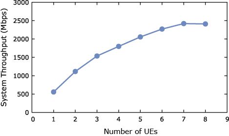
We performed these measurements multiple times with different numbers of terminals to evaluate the total throughput versus the number of simultaneous multiple connections.
For example, when conducting the experiment with 2 UEs, 2 of the 8 UEs were selected. In this case, there are 8C2 = 28 combinations, some of which are selected for the experiment. Although we did not cover all combinations, we experimented with many combinations and estimated and calculated the total throughput in each case and evaluated it as the average throughput for the number of UEs. As the number of UEs increases, the MSE degrades, but due to the close distance, the received level at each UE is not low enough to affect the thermal level. This degradation is expected to be primarily due to interference caused by insufficient spatial separation capability. Fig. 8 shows the average throughput versus the number of UEs. It can be seen that throughput increases linearly with the number of streams up to 3 or 4 MIMO streams, but tends to saturate above that, with maximum throughput being achieved at around 7 multiplexes.
4. Conclusion
In the 39 GHz band, a prototype AAS with hybrid beamforming capability using 256 antenna elements was verified. In the experiment assuming mobile access, an OFDM 8 MU-MIMO connection was achieved at 100 MHz Band Width, and a system throughput of 2.42 Gbps was obtained, demonstrating the feasibility of Massive MIMO at 39 GHz.
5. Acknowledgement
This work was supported by the Japanese Ministry of Internal Affairs and Communications (JPJ000254).
We also express the acknowledgements to Prof. Kenichi Okada and the researchers in his laboratory at Tokyo Institute of Technology for their contributions.
References
- 1)T. L. Marzetta: Massive MIMO An Introduction, in Bell Labs Technical Journal, vol.20, pp.11-22, 2015
- 2)M. Hayakawa, T. Mochizuki, M. Hirabe, T. Kikuma and D. Nose: Effect of Nonlinear Distortion and Null Stability on Spatial-multiplexing Performance using 4.65-GHz-Band Active Antenna System with DPD, 2019 49th European Microwave Conference (EuMC), pp.1076-1079, 2019
- 3)T. Kuwabara, N. Tawa, Y. Maruta, S. Hori and T. Kaneko: A 39 GHz MU-MIMO using 256 Element Hybrid AAS with Coherent Beam-Forming for 5G and Beyond IAB Applications, 2021 51st European Microwave Conference (EuMC), 2022
- 4)J. Pang et al: A 28-GHz CMOS Phased-Array Beamformer Supporting Dual-Polarized MIMO with Cross-Polarization Leakage Cancellation, in IEEE J Symposium on VLSI Circuits, 2020
- 5)T. Kuwabara, N. Tawa, Y. Tone and T. Kaneko: A 28 GHz 480 elements digital AAS using GaN HEMT amplifiers with 68 dBm EIRP for 5G long-range base station applications, 2017 IEEE Compound Semiconductor Integrated Circuit Symposium (CSICS), pp.1-4, 2017
- 6)N. Tawa, T. Kuwabara, Y. Maruta and T. Kaneko: 28 GHz Distributed MIMO Comprehensive Antenna Calibration for 5G Indoor Spatial Division Multiplex, 2021 IEEE MTT-S International Microwave Symposium (IMS), 2021
Authors’ Profiles
KUWABARA Toshihide
Senior Professional
Wireless Access Development Department
Senior Professional
Wireless Access Development Department
TAWA Noriaki
Professional
Wireless Access Development Department
Professional
Wireless Access Development Department
MARUTA Yasushi
Senior Professional
Wireless Access Development Department
Senior Professional
Wireless Access Development Department
HORI Shinichi
Professional
Wireless Access Development Department
Professional
Wireless Access Development Department
KANEKO Tomoya
Senior Professional
Wireless Access Development Department
Senior Professional
Wireless Access Development Department