Global Site
Displaying present location in the site.
Development of a Video Wall Display System Using Ultrathin-Bezel LCD Panels
Vol.6, No.3 October 2011, Imaging and Recognition SolutionsPublic display systems are being expanded with the introduction of large video wall displays.
NEC Display Solutions has developed a video wall display system featuring a multi-screen display using ultra-thin bezel LCD panels. This paper introduces the salient features of this system.
1. Introduction
Public display systems are now being used as information boards in airports and railway stations as well as for digital signage in shopping malls and applications as video wall displays of larger size are also expanding.
On the other hand, the large-screen LCD panel as a single unit is limited in its screen size (around 100-inch) and thereby poses problems in transportation, installation and maintenance.
In order to deal with these issues, NEC Display Solutions have developed a video wall display system based on a multiscreen display that combines up to a hundred LCD panels (10 vertical × 10 horizontal) with ultrathin bezels that form a large-screen with various formats including 460/550 inch large screens as well as horizontally and vertically wide screens.
Below, we introduce features of the video wall display system that uses the newly developed X462UN ( Photo ) and X551UN LCD panels.
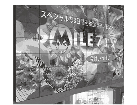
Photo Multi-screen display using X462UN panels.
2. Issues of Multi-screen Display
The main issues in implementing a multi-screen display using multiple display panels are as follows.
- Improvement of display quality (including the quality of each display panel and in variance due to individual differences between panels).
- Ease of installation.
- Centralized control of multiple display panels.
The procedures used to resolve these issues will be described in sections 3 to 5 below.
3. Improvement of the Display Quality of Multi-screen Displays
3.1 Adoption of Ultra-thin Bezel LCD Panel
In order to minimize the non-displayed area between adjacent display panels due to the bezels in the multi-screen configurations, we adopted ultra-thin bezel LCD panels. As a result of the very narrow bezel widths, of 6.7 mm for the 46-inch model (Left/Top 4.3 mm, Right/Bottom 2.4 mm) and 5.5 mm for the 55-inch model (Left/Top 3.7 mm, Right/Bottom 1.8 mm), the multi-screen display succeeded in making the splices between display panels less noticeable ( Fig. 1 ).
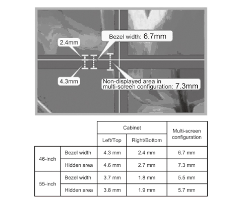
Fig. 1 Bezel widths and non-displayed joints in multi-screen configurations (Photo: 46” display).
3.2 Improvement in Abnormalities between Displayed Panels (TILE COMP)
When an image is displayed on a multi-screen system, the connection between parts of an image tends to look unnatural due to the bezels of the display panels. In order to deal with this issue, we incorporated the TILE COMP function, which smoothes the connection of images between display panels by automatically optimizing the image areas hidden by the bezels according to the number of display panels installed horizontally and vertically ( Fig. 2 ).
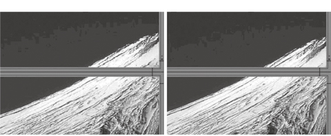
Fig. 2 Comparison between TILE COMP OFF (Left)/ON (Right)
3.3 Improvement of Brightness Anomalies (EDGE COMP ® )
The uniformity of brightness of each display panel varies due to the backlight configuration, with the brightness near to the bezels being reduced compared to that of the center of the panel. As this phenomenon is particularly noticeable with the newly adopted ultra-thin bezel LCD panels (CCFL backlight), brightness anomalies as shown on the left of Fig. 3 tend to be observed in the multi-screen configuration. To reduce such anomalies, we incorporated the EDGE COMP ® function in the X462UN.
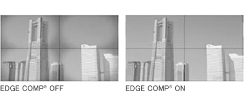
Fig. 3 Comparison between EDGE COMP® ON/OFF.
This function compensates for brightness anomalies at the edges of each panel by correcting the video signal. It can adjust the brightness both at the panel center and at the panel edges respectively in three steps ( Fig. 4 ), according to the individual difference in the brightness anomaly of each display panel. This correction reduces the brightness at the panel center at the same time as decreasing brightness anomalies around the bezels, thereby rendering the image easier to view with little malformation.
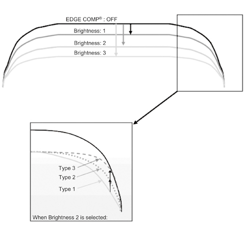
Fig. 4 Image of EDGE COMP® correction.
3.4 Improvement of Brightness and Color Temperature Anomalies (Wall Calibration)
Variances in brightness and color temperature due to individual differences between display panels are particularly noticeable in multi-screen display systems.
In an attempt to resolve this issue, we incorporated the Wall Calibration function, with which a PC that has dedicated calibration software “NEC Display Wall Calibrator” installed is connected via RS232C or LAN. The brightness/color temperature/gamma values are thereby adjusted using a commercially available and NEC approved color sensor.
The display uses internally generated test patterns for auto adjustment and does not need a video input device for adjustments. The display panel can usually be adjusted in about 2 minutes and in 2 to 6 minutes in cases for which adjustment options such as more accurate gray scale and low-gradation adjustments are selected.
The NEC Display Wall Calibrator supports three kinds of brightness adjustments and is capable of matching color and brightness on every display panel of a multi-screen configuration, adjusting the brightness and color temperature to the specified values and adjusting the brightness of each display panel to the maximum possible level.
The software also offers many functions and options that make it flexibly usable in a wide range of visual applications including the support of medical imaging with DICOM (Digital Imaging and Communications in Medicine).
4. Pursuit of Ease of Installation
Installation of a large video wall unit necessitates optimally arranged panel placement as shown in the photograph above. The display panels are usually installed by means of dedicated hardware attached at their rears.
The conventional installation hardware was equipped with adjustment mechanisms for the up/down, left/right, front/rear and tilting adjustments so that the positioning of each display panel can be adjusted independently. However, a too high degree of freedom of adjustment (too many axes) tends to extend the time required for adjustments and sometimes makes correct positioning difficult. Particularly, the front/rear adjustment (height differences between panels) is extremely difficult.
We solved this problem by developing a set of hardware that facilitates the panel positioning while reducing the freedom of adjustment (wall mount kit).
4.1 Configuration of the Wall-mount Kit
The wall-mount kit is composed of brackets attached to the four corners at the rear of the display panel as shown in Fig. 5 , and of brackets mounted on the wall as shown in Fig. 6 . The wall mount brackets have pins for fitting into the panel bottom brackets at the corners.
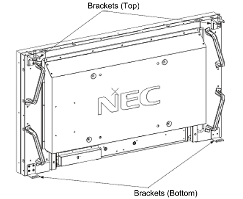
Fig. 5 Brackets at the four corners of the rear of display panel.
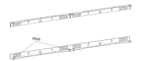
Fig. 6 Wall mount brackets (Example: brackets for two units).
4.2 Installation and Adjustment Procedures
Firstly, fit the display panel on the wall mount brackets as shown in Fig. 7 .
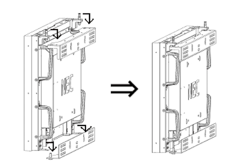
Fig. 7 Installing the display on the wall-mounted brackets.
The brackets (top) have adjustment pins as shown in Fig. 8 . These are threaded pins so that the display panel can be moved up/down by turning them appropriately. The left and right pins can be turned independently so that the panel inclination can also be adjusted.
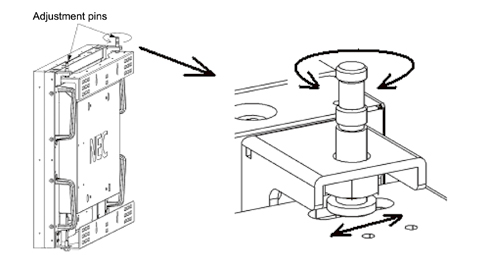
Fig. 8 Adjustment pins (Up/Down adjustment and Left/Right sliding).
The display panels of the same row are installed using the same procedures as described above. As the holes on the wall-mounted brackets in which the adjustment pins are inserted are rectangular (Fig. 8, Right), the clearance between two adjacent display panels can be adjusted by sliding the pin insertion position either to the left or the right.
After completing installation of the display panels in the horizontal direction, other display panels may be stacked on them ( Fig. 9 ).
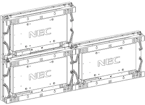
Fig. 9 Image of installation (Rear view).
The bottom bracket of each display panel in the upper row can be coupled with the adjustment pins of the display panel below it ( Fig. 10 ). This makes it possible to automatically adjust the panel positioning in the front/rear positions so that the adjustment of height differences between panels, which used to be difficult work with the previous design, is no longer necessary. The clearance between the display panels on the upper and lower rows can also be adjusted by turning the adjustment pins in the same way as described above.
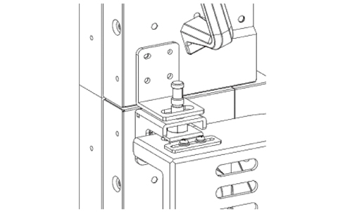
Fig. 10 Coupling of Up/Down displays using adjustment pins.
The weight of each display panel is supported by its own wall-mounted brackets so that the display panels in the lower row do not bear an imposed load.
By repeating the operations described above, a large video wall can easily be constructed, without the need for complicated adjustments.
5. Improved Operability
5.1 Daisy Chain Connection and ID Numbering of Remotely Controlled Units
The newly developed display panels have a remotely controlled light sensor at the rear bottom in order to minimize the bezel width. As a result, this design makes it difficult to remotely control the panel when it is used in a multi-screen display system.
Therefore, we provided the remote control IN/OUT terminals as shown in Fig. 11 so that a remote control light sensor unit (optional) can be connected and installed in any position. Additionally the display panels are daisy chain connected with remote control cables so that all of them can be controlled from a single light sensor unit.
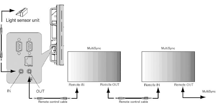
Fig. 11 Control using external light sensor unit.
The display panels and remote control units incorporate ID setting functions. When IDs are set to the remote control units, each remote control unit can control only those display panels of the same ID ( Fig. 12 ).
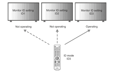
Fig. 12 Remote control in ID mode.
5.2 Centralized Management via RS-232C/LAN
Centralized management of the display panels is possible using the RS-232C serial communication. Just as in the case of the remote control of multiple display panels, IDs can be assigned to the display panels and various settings can be made from a computer via a daisy chain connection of the RS-232C cables ( Fig. 13 ).
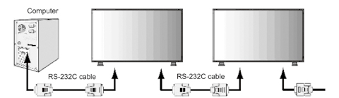
Fig. 13 RS-232C control using a PC.
When the display panels are connected via a LAN, the support of the SNMP (Simple Network Management Protocol) allows them to be controlled by centralized management.
6. Conclusion
At NEC Display Solutions, we aim to improve video wall display systems based on multi-screen displays by using ultra-thin bezel LCD panels and to thereby develop products that can offer solutions for a variety of usage scenarios of the future.
Authors' Profiles
OGAWA Koutarou
Manager
2nd Development Group Monitor development Division NEC Display Solutions, Ltd.
Manager
2nd Development Group Monitor development Division NEC Display Solutions, Ltd.
MITSUHASHI Renichi
2nd Mechanical Engineering Department
Common Technical Platform Development Division NEC Display Solutions, Ltd.
2nd Mechanical Engineering Department
Common Technical Platform Development Division NEC Display Solutions, Ltd.