Global Site
Displaying present location in the site.
Hayabusa2: System Design and Operational Results
Cutting-edge Technologies to Build a Better Future: Advanced Technologies in Space Applications PDF
PDFNEC played a leading role in the development and manufacture of the Hayabusa2 asteroid explorer, not only designing the system, integrating equipment, conducting tests, and providing operational support, but also coordinating the development of the subsystems for the spacecraft’s structure, thermal, power supply, telecommunications, data handling, attitude/orbit control, ion engine, electric instrumentation, and sampling systems. NEC supplied some of the components for these subsystems as well as several of the observation devices. This paper discusses the role NEC played in the Hayabusa2 project and discusses operational scenarios and results in the vicinity of asteroid Ryugu as well as the factors that contributed to the mission’s success.
1. Introduction
As it did with the first Hayabusa, NEC supplied many subsystems and devices to the Hayabusa2 asteroid explorer and took responsibility for much of the project’s system design, integration, testing, and operational support. More reliable and more functional than the first Hayabusa, Hayabusa2 was launched in December 2014, arriving at the asteroid Ryugu in 2018. From June 2018 to December 2019, it conducted asteroid proximity operations and brought back a re-entry capsule to Earth in December 2020. This paper introduces Hayabusa2’s system, operational results, and factors that contributed to the success of the mission.
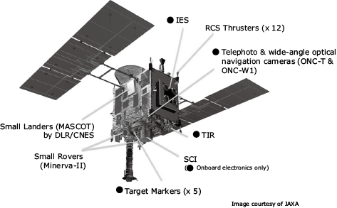
2. Structure of the Spacecraft
An external view of the Hayabusa2 is shown in Fig. 1 and Fig. 2. All devices marked with a black circle (•) were the responsibility of NEC. The main differences from the first Hayabusa are that the high gain antenna was changed from parabola to a radial line slot array antenna and that a Ka band antenna (down link bit rate increased by a factor of 4) was provided in addition to the X band antenna.
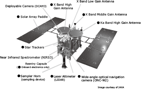
Based on the assumption that Haybusa2 approach the asteroid from Earth’s direction (nearly equal to the Sun’s direction), the solar array paddles and high gain antennas were installed on the top, whereas the sensors to observe the asteroid and the other devices that would be released and deployed on the asteroid as well as the sampler horn were installed on the bottom.
Also assuming that the change in velocity (delta-v) would take place perpendicular to the sun, the thrust direction of the ion engine system (IES) was set in an almost perpendicular direction to the sun. The IES’s thrusters were mounted on two-axis gimbals. By changing the thrust axis around the center of gravity of the spacecraft, two-axis torque control by the IES was made possible. This was also used in the unloading (rotation speed adjustment) of the reaction wheel for attitude control.
NEC supplied almost all of the devices installed inside the spacecraft in addition to those mentioned earlier. The subsystems that NEC was responsible for are listed here.
- (1)Power supply subsystem to generate power from sunlight and to perform voltage adjustment, power storage, power distribution, and current limiter functions
- (2)Telecommunication subsystem to perform two-way communications with Earth
- (3)Data handling subsystem to perform command processing and telemetry processing
- (4)Attitude and orbit control subsystem to control the spacecraft’s attitude and orbit
- (5)Ion engine subsystem to control the spacecraft’s orbit from Earth to the asteroid (excluding the Xe supply system)
- (6)Devices needed to carry out the mission: optical cameras, thermal infrared imager (TIR), digital electronic device that controls each camera, and sampler
- (7)Electrical circuits of the small carry-on impactor (SCI) to create an artificial crater and of the re-entry capsule to bring samples to Earth
- (8)Thermal control subsystem that keeps every section of the spacecraft at an appropriate temperature
- (9)Body structure that holds the devices through vibrations and shocks during launch
- (10)Electric instrumentation that connects the devices
In addition to these, we also conducted the overall system design, integration, and testing, as well as operations support including the devices made by other companies such as science payloads, the reaction control system (RCS) and the Xe supply system.
3. Planned Touchdown Scenario
The touchdown scenario we had originally planned before Hayabusa2 arrived at asteroid Ryugu was as follows.
- (1)Descend to a wide flat area about 100 m in diameter.
- (2)Drop target marker (TM) on the asteroid’s surface for use as landmarks in the surface synchronization process.
- (3)Drop TM during touchdown sequence and then immediately execute touchdown.
- (4)Align with the asteroid’s surface based on the distance measurement data from the four beams generated by the laser range finder (LRF) .
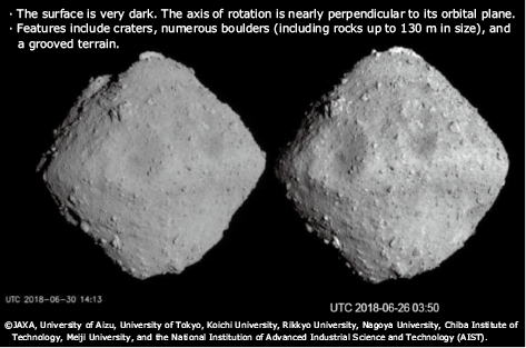
4. Shape of Asteroid Ryugu
An external view of asteroid Ryugu is shown in Photo 1. The entire surface was covered with rugged boulders. Nowhere could we find a flat area measuring 100 m in dimeter that we had assumed would be found.
Source: JAXA’s press conference material
(July 19, 2018).
Other features of Ryugu are as follows.
- (1) Size:Equatorial diameter ― 1,004 m
Polar diameter ― 875 m - (2) Rotation period:Approx. 7 hours 38 minutes
- (3) Rotation axis orientation: Almost perpendicular to the asteroid’s orbital plane of revolution
- (4) Rotation direction:Opposite to Earth
- (5) Reflectance:0.05 (blackish look)
- (6) Type:C (possibly containing water and organic matter)
- (7) Orbital radius :Approx. 180 million km
- (8) Orbital period:Approx. 1.3 years
5. Proactive Measures for the First Touchdown
We took the following measures proactively to deal with any unforeseen situations.
- (1)Dropping the TMs and confirming their locations in advance to perform positional control relative to the TMs from the beginning
- (2)Landing with the tail up to avoid rocks by tilting the attitude of the spacecraft so that it could be adjusted in accordance with information specific to the landing location obtained before landing.
- (3)Having the spacecraft learn the local planes of the planned landing location, because the plane estimation using the four beams of the LRF would be strongly affected by rocks
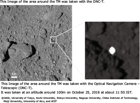
The dropped TM and its environs are shown in Photo 2.
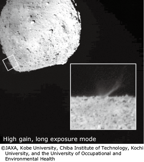
6. The First Touchdown
Our proactive measures were effective and the Hayabusa2 successfully touched down on Ryugu at 7:29 JST on February 22, 2019. The asteroid’s surface was nothing like we anticipated. The surface was very friable, and fragments flew up like swirling confetti. These fragments were very black and dirtied the lenses of the optical sensors. The LRF was especially affected. Subsequent checks showed that its distance measurement range had been reduced and that the distance measurement characteristics also changed.
7. Proactive Measures for the Second Touchdown
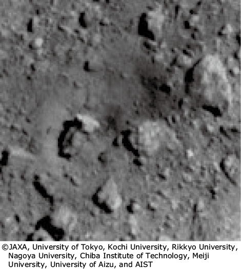
After creating an artificial crater with the SCI, Hayabusa2 made a second touchdown in a location where subsurface material was likely present. A view of the artificial crater is shown in Photo 3 and Photo 4.
We took the following proactive measures to support the second touchdown.
- (1)Confirmed the distance measurement range and characteristics of the LRF in advance to compensate for changes and reduced the usage altitude of the LRF
- (2)Checked the degree of blurriness of the images from the wide-angle optical navigation camera (ONC-W1) in advance and adjusted the sequence accordingly ― specifically by decreasing the TM capturing altitude
- (3)As a result, there was a gap between the lower limit of the LIDAR (laser altimeter) range and the upper limit of the LRF range, but we took careful measures to avoid collisions, including setting a time limit with a timer.
- (4)Because the safety of the spacecraft is our top priority, we set the spacecraft to immediately abort any operation in progress whenever necessary and escape to a safe location.
8. Results of the Second Touchdown
The second touchdown was successfully completed at 10:06 JST on July 11, 2019. This resulted in two achievements unprecedented in space exploration: sampling from two locations and access to underground material.
9. The Elements of Success 1: Careful Preparation
A lot more work went into preparing the Hayabusa2 for landing than was the case with the original Hayabusa.
- (1)Operation plans were created that corresponded to the various descent operations that could be foreseen. Situational changes and new ideas were included in these operation plans. Discussions with the Japan Aerospace Exploration Agency (JAXA) were reflected in the operation plans, which were revised frequently.
- (2)Based on the operation plan, a procedure manual was prepared for each day. Contingency strategies were also included in these manuals. All operations were based on these manuals.
- (3)Computer simulations based on the procedure manuals were run to test out how actual operations would be executed. The dynamics of the spacecraft were calculated, commands verified, and parameters validated.
- (4)Hardware-in-the-loop (HIL) simulations that combined the flight controller and the spacecraft’s prototype were performed to verify the procedures in the manuals.
- (5)In conjunction with the HIL simulation, operation drills were performed to test and train under conditions with potential problems.
10. The Elements of Success 2: Teamwork That Produced Results
Teamwork is critical to success and in this case everyone was involved in the operations.
- (1)Relationships were built which facilitated frank discussion. This applied not only to NEC members but to clients as well. Everyone contributed in the areas where they were strong and utilized other people’s strong points.
- (2)Everyone was convinced that the project would absolutely achieve success aspired and prioritized the overall success of the project rather than individual gain. That way, everyone wins.
- (3)While remaining committed to ensuring the safety of the spacecraft, everyone was prepared to take risks to achieve operational success. Everyone maintained a positive attitude even when encountering disappointment such as when the spacecraft was forced to abort an operation and return to the home position without accomplishing the scheduled task.
11. Conclusion
Hayabusa2’s re-entry capsule returned safely to Earth on December 6, 2020, bringing with it a rich collection of material samples and gasses (5.4 g). The spacecraft is now on its way to asteroid 1998KY26 (with a diameter of 30 m and a rotation period of 10.7 minutes) where it is scheduled to arrive in July 2031. Prior to that, it is planned to fly by asteroid 2001CC21. Building on the experience gained in the development and operation of Hayabusa and Hayabusa2, NEC will continue to develop systems for deep space exploration and asteroid exploration.
Finally, we would like to express our gratitude to JAXA who has guided and supported NEC throughout the development process and the actual mission operations.
Author’s Profile
OSHIMA Takeshi
Project Director
Space Systems Division
Project Director
Space Systems Division