Global Site
Displaying present location in the site.
Spaceborne LIDAR-Supported Autonomous Landing of Hayabusa2 Spacecraft with Remote Sensing Technology
Cutting-edge Technologies to Build a Better Future: Advanced Technologies in Space Applications PDF
PDFAs more and more countries compete to launch deep space exploration missions, such as the one Japan’s Hayabusa2 asteroid explorer is on, light detection and ranging (LIDAR) is becoming one of the advanced technologies facilitating this new wave of lunar and planetary exploration. Ever since the Apollo program, LIDAR has been used to determine the altitude of a spacecraft as well as for topographical survey of various astronomical objects. It was also incorporated in the selenological and engineering explorer (SELENE) nicknamed Kaguya and will be in the Martian Moons eXploration (MMX) vehicle set for launch in 2024. In this paper, we will introduce the LIDAR technology developed by NEC for space exploration and its current status as of 2021.
1. Introduction
Having made two successful landings on the asteroid Ryugu, the Hayabusa2 spacecraft returned to Earth with samples from this distant asteroid. In deep space where navigational support such as GPS are not available and real-time control from Earth is not possible, light detection and ranging (LIDAR) plays a critical role in facilitating the autonomous functions of the spacecraft.
This paper introduces the LIDAR developed by NEC that was used in the Kaguya lunar explorer and the Hayabusa2 asteroid explorer as well as the LIDAR technology that is currently under development as of 2021 for the upcoming mission for Martian moons eXploration (MMX)1).
2. Laser Altimeter on Kaguya
The selenological and engineering explorer (SELENE) nicknamed Kaguya was launched in September 2007. After completing nominal and latter phase operations in lunar orbit that spanned about a year and a half, Kaguya impacted to the moon’s surface in June 2009.
Kaguya’s laser altimeter (LALT)2) enabled detailed mapping of lunar topography by observing the distance and reflectance from a nominal altitude of 100 km from the surface of the moon. Periodic corrections were made to the orbit which varied between 50 km and 150 km due to gravitational effects. Kaguya was also the first lunar exploration craft to successfully collect data from the moon’s poles. That data is now being used to more accurately estimate the moon’s gravity among other applications.
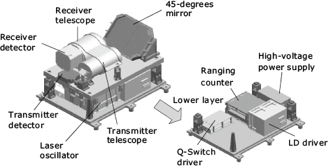
Kaguya’s LALT is divided into two units (Photo 1). The total mass is 19.1 kg, the power consumption is 44.2 W, and the range resolution is 1 m. The internal structure of the laser transmitter/receiver (LALT-TR) that transmits and receives light is shown in Fig. 1.
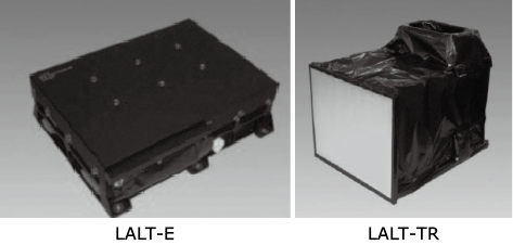
LALT-TR laser transmitter/receiver (right).
With its laser output in the 100-mJ class, the LALT generates an unusually large amount of energy for a spaceborne laser. Because LALT compensates for the peak value of the received pulse that drops because of slopes and irregularities, it can more effectively acquire altitude data for the moon’s surface whose rugged topography features frequent changes in elevation.
The LALT-TR, which transmits and receives lasers, is constructed in two sections as shown in Fig. 1. Optical devices that need to avoid thermal strain are in the top half, and various heat-generating driver circuits are in the bottom half. Kinematic mounts are used for joining the two sections as well as for the installation of the laser oscillator and the transmitter/receiver telescopes to minimize the effects of distortion from thermal distribution.
The laser oscillator is a neodymium-doped yttrium aluminum garnet (Nd:YAG) type with a pulse energy of 100 mJ, a pulse width of 17 ns, and a Q-switching with a pulse repetition rate of 1 Hz. The optical layout of the laser oscillator is shown in Fig. 2.
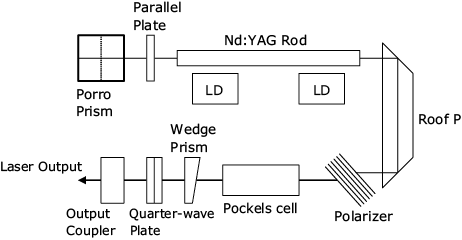
The pump module has laser diodes (LDs) for laser crystal and pumping. The LDs are arranged on the sides of an Nd:YAG rod in eight directions to maintain uniform pumping. Because the module operates in a vacuum, a non-coated polarizer helps compensate for any alterations to characteristics when evaluated in the atmosphere. The Q-switching, which uses lithium niobate (LiNbO3) in the Q-switching element, is an active Q-switching that combines a quarter wave plate and a Pockels cell operating at a quarter wavelength. The dimensions of the laser oscillator are 150 x 170 x 83 mm, and the mass is approximately 1.6 kg.
The transmitter telescope and the receiver telescope both have lens barrels made of carbon fiberglass reinforced plastic (CFRP) and share a transmitter/receiver to achieve a lightweight design. The receiver optics uses a 110-mm aperture Cassegrain telescope made of quartz; the transmitter optics uses a 10X Galilean telescope.
While Kaguya was in orbit, the LALT made a total of about 2,200 laser shots during its 18-month mission. This data is now used for research into the origins of the moon and how it evolved over time as well as research into the development of the moon’s resources.
3. LIDAR for Hayabusa2
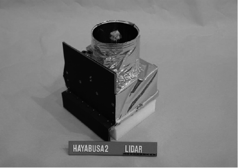
Featuring an observation range from 30 m to 25 km, a total mass of 3.52 kg, a power consumption of 18 W, and a range resolution of 0.5 m, Hayabusa2’s LIDAR3) was used to map the asteroid Ryugu and for navigation support until immediately before touchdown. It was also used for the measurement of reflectance and various other observation tasks. An external view of the LIDAR is shown in Photo 2.
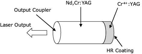
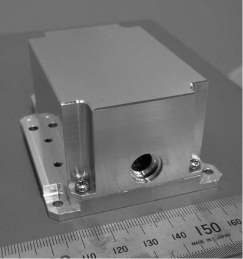
The laser oscillator is an Nd:YAG type with a pulse energy of 15 mJ, a pulse width of 7 ns, and a Q-switching with a pulse repetition rate of 1 Hz. Based on the experience from the first Hayabusa and Kaguya, the Q-switching uses a passive system to avoid the pyroelectric effect of LiNbO3 resulting from thermal stress in a vacuum. The oscillator contains a single optical element that uses a composite crystal bonded with a laser medium and a passive Q-switch element (Fig. 3). This monolithic resonator helps reduce the risks of misalignment and optical damage. The laser oscillator’s dimensions are 66 x 90 x 40 mm and weighs 190 g, so it is compact enough for the asteroid explorer in resource-intensive space travel. An external view of the laser oscillator is shown in Photo 3.
(engineering model).
The optical system is divided into two subsystems to assure the dynamic range of the receiver system with its 30-m to 25-km observation range. Gain adjustment is performed by a detector for each subsystem. The area ratio of the far-range and near-range optical subsystems is 1345:1. Distance measurement accuracy is assured throughout the 30-m to 25-km observation range by varying the distance in four steps in combination with 2-step switching of the reverse bias voltage of the avalanche photodiode (APD). Gain switching is performed autonomously by automatic gain control (AGC) which detects the detection level.
The receiver in the far-range subsystem uses a Cassegrain telescope with a 127-mm aperture and a 110-mm aperture when the shielding loss is taken into consideration. The material used for the receiver is new-technology silicon carbide (NT-SiC) developed for space applications to reduce the mass. The transmitter is equipped with a 3X expander, and the beam divergence angle after transmission is 2.4 mrad. In addition to the standard distance measurement mode, LIDAR operation modes include a dust count intended for scientific observation and an optical link to conduct optical link experiments with a satellite laser ranging (SLR) station on Earth. As of January 2021, LIDAR had taken about 7.11 million laser shots in orbit. LIDAR is also expected to play a prominent role in the next stage it is used.
4. LIDAR for the MMX mission
The MMX explorer is now under development (as of 2021) and is set for launch in 2024. Current plans call for to land on the Martian moon Phobos where it will collect samples for return to Earth. The observation range of the MMX’s LIDAR is from 100 m to 100 km with a dynamic range equivalent to Hayabusa2’s 60 dB.
For the most part, the LIDAR used for the MMX mission is the same as that used by Hayabusa2. The MMX’s LIDAR, however, features increased laser output and improved receiver circuits. As mentioned earlier, Hayabusa2’s optical system is divided in two for far distances and close distances. Now, thanks to the completion of the IC LIDARX developed by the Japan Aerospace Exploration Agency (JAXA) specifically to provide wide a dynamic range, a single optical system4) has been achieved for the upgraded LIDAR used in the MMX mission. The circuit configuration of the LIDARX is shown in Fig. 4.
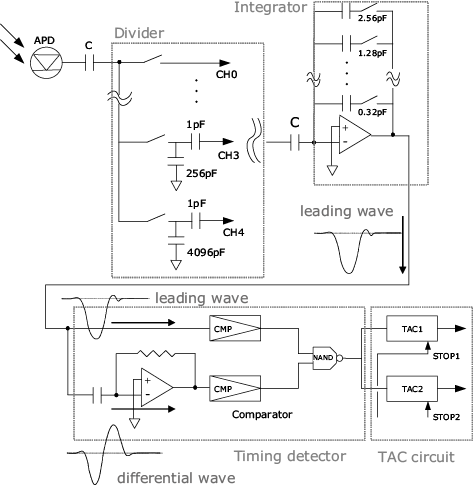
LIDARX is composed of a divider, an integrator, a timing detector, and a time-to-analog converter (TAC) circuit. The divider selects the appropriate amount of electric charge and divides it for APD output which varies according to the measured distance. The input electric charge is current-voltage converted by the integrator to generate leading waves. The leading waves are converted into differential waves at the differential circuit of the timing detector. The zero-cross point is detected as signal timing. The detected timing is converted to analog signals at the TAC circuit and the distance is output as analog level signals. By using the TAC circuit, high range resolution can be achieved without using a high-speed clock which is difficult to handle in a space device.
Like Hayabusa2’s LIDAR, the MMX’s LIDAR uses an Nd:YAG laser with a passively Q-switch. The laser output has a pulse energy of 20 mJ or more, a pulse width of 10 ns or less, and a repetition rate of 1 Hz. Our goal is to achieve a device with a mass of 4.7 kg or less and range resolution of 0.1 m or less.
As of 2021, the partial prototype evaluation of the critical section has been completed and we are now proceeding with the development of the engineering model for technological evaluation before the creation of the final flight model.
5. Conclusion
Over the past two decades, NEC’s LIDAR technology for lunar and planetary exploration has continued to evolve, beginning with Kaguya, progressing through Hayabusa2, and culminating with the MMX mission. While it has proven itself in space exploration missions, this versatile technology can also be applied to spacecraft or devices used for missions other than exploration. As of 2021, development of a LIDAR system to facilitate docking of a cargo spacecraft is underway and LIDAR is expected to play an active role in a wide range of space missions in the future.
Finally, we would like to express our heartfelt gratitude to JAXA, the National Astronomical Observatory of Japan, and the Chiba Institute of Technology — all of whom keep us up to date on the latest projects and enable us to improve the devices under development — as well as the manufacturers who have given us invaluable support.
Reference
- 1)Teiji Kase, et al.: Lidar for Lunar and Planetary Exploration, Journal of Laser Radar Society of Japan, Volume 2, Number 1, April 2021
- 2)H. Araki et al.: Lunar Global Shape and Polar Topography Derived from Kaguya-LALT Laser Altimetry, Science, Vol.323, 2009
- 3)T. Mizuno et al.: Development of the Laser Altimeter (LIDAR) for Hayabusa2, Space Science Reviews, Vol.208, 2017
- 4)T. Mizuno et al.: Pulse Detection IC for a Laser Altimeter Using CMOS Technology, Transactions of the Japan Society for Aeronautical and Space Sciences, Aerospace Technology Japan, Vol. 10 No. ists28, 2011
Authors’ Profiles
KASE Teiji
Assistant Manager
Radio Application, Guidance and Electro-Optics Division
Assistant Manager
Radio Application, Guidance and Electro-Optics Division
MAYUZUMI Katsunori
Manager
Radio Application, Guidance and Electro-Optics Division
Manager
Radio Application, Guidance and Electro-Optics Division
IKUSE Yasuyuki
Radio Application, Guidance and Electro-Optics Division
Radio Application, Guidance and Electro-Optics Division
 Hayabusa2 Project