Global Site
Displaying present location in the site.
Observation of Internal Structures Using Muography
Sensing Technologies Underlying Social Systems: Sensing Technologies That Work Behind the Scenes PDF
PDFImaging of internal structures using an elementary particle called a muon is called muography. Operating in the same way as radiography, muography offers non-destructive imaging thanks to the high penetrability of the muon particle. In this paper, we explain how a muon detector works and how internal structures can be apprehended using machine learning. We also discuss the various fields in which muography can be applied and NEC’s efforts to develop a muography system.
1. Introduction
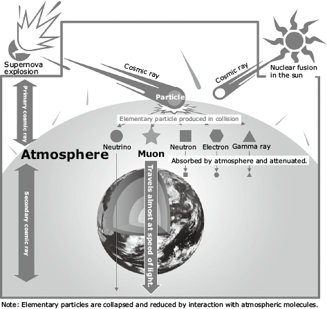
A muon is an elementary particle that is one of the components of cosmic rays (Fig. 1). Muography is a technique that leverages the muon’s high penetrability to facilitate non-destructive imaging of the internal conditions of an object or structure in much the same way as medical radiography. The first thing that distinguishes muography from existing sensors is that the size of objects that can be observed varies widely ― ranging from a few meters to a few kilometers. The other thing that is important is that muography is not restricted by time or location as it uses cosmic rays ― which is all around us all the time ― as a probe. In other words, no energy source is required for the probe, virtually eliminating any running costs.
This paper first describes the basic principles of muography1) and shows how the detector NEC is developing will work together with machine learning to provide a coherent and comprehensive visualization of internal structures. We then discuss potential applications for this technology and future prospects.
2. Sensing Principles
Muons are captured using a muon detector, which is described in section 3. The number is counted according to the travel direction. Fig. 2 shows the relationship between zenith angle θ ― where the zenith direction of the detector per unit area is used as a reference axis ― and azimuth angle φ on the horizontal plane. It is known that the number of muons falling from the sky to the surface of the earth depends only on θ in Fig. 2 and is uncorrelated with φ.
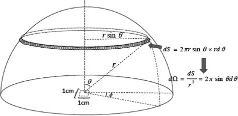
A muon that passes through matter loses energy. How much it loses depends on the type and density of the matter in its path. If a large amount of energy is lost, then the scattering of matter with atomic nuclei and electrons in the muon’s path will also be large. As a result, the muon’s path will deviate from the detector. This phenomenon is observed by the detector as a decrease in the number of muons. Thus, the sensor measures the number (flux) of muons per unit time, solid unit angle, and area in each θ and φ in Fig. 2. By comparing this result with the muon flux known on the surface of the earth, it is possible to visualize the internal condition of the material object ― between the sensor and the surface of the earth ― in the form of density distribution.
3. Muon Detector
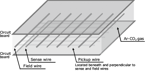
The detector used for muography is a gaseous detector called a multi-wire proportional chamber (MWPC)2). The MWPC consists of two circuit boards held at ground potential, two types of wires (sense wires and field wires) that are stretched between the circuit boards at regular intervals, and wires (pickup wires) that intersect those two types of wires at right angles (Fig. 3). When the detector operates, mixed Ar and CO2 gas is pumped into the space between the two circuit boards. When a high voltage is applied to the sense wires, a strong electric field is created between the two circuit boards.
When the muon passes through the detector, Ar molecules on its path are ionized (Fig. 4 (1)). The ionized Ar moves towards the field wires and pickup wires and the electron moves towards the sense wires while being accelerated in the electric field (Fig. 4 (2)). The electron in transition collides with the Ar molecule and ionizes that molecule (Fig. 4 (3). When this process is repeated continuously as if creating an avalanche, large numbers of electrons accumulate around the sense wires (Fig. 4 (4)) and are sent to the electric circuit as large signals. These electrons are taken in by the Ar ions to the original form of the Ar molecule.
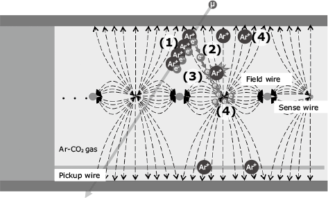
Since the electrons produced by muons concentrate on the wire closest to where they have passed, the path of the muons can be determined according to the position of the wire which has read out the signals. Hence, by stacking MWPCs in multiple layers, the trajectories of the muons can be determined.
MWPCs use narrow-diameter wires. Sense wires used for generation of an electric field inside an MWPC measure about 50–60 µm across and the field wires used for acquisition of travelling position information measure about 100 µm across. Numerous wires are required. The sense wire is usually made of tungsten, and the field wire from copper. However, tungsten has poor soldering properties, which often leads to failure when an unsoldered wire contacts the internal surface of the MWPC. This is one of the main drawbacks of MWPCs. By comparing and examining multiple wire surface coating and soldering techniques, NEC was able to significantly improve the soldering properties. Examination of a defect detection method when the sensor is mass-produced is also underway.
To sense the internal structure of matter using muography, the configuration and layout of the sensor must be adjusted according to the observation target in order to obtain the requisite angle of view and observation resolution. NEC’s MWPC has a sensor section and signal processing section whose dimensions are compatible with 19-inch racks (EIA standard). Once the configuration has been modified according to the application, observation at the optimum angle of view is possible. MWPC can also be housed in EIA-compatible portable racks that are waterproof, dustproof and environmentally durable, allowing you to perform muography even in difficult environments such as outdoors as well as underground shafts and galleries. This rack is a metallic housing with excellent shielding properties, so when combined with an anti-noise shield installed in each chamber, it can keep out any external electric noise that might affect muon detection.
4. Information Extraction by Machine Learning
The muon flux obtained from the muon detector needs to be converted into information that can be used by the application. When applied to volcano monitoring, for example, this information could show the density contrast between magma and bedrock. When applied to production facility monitoring, it could show the degree of wear and tear of various components. In this section, we are going to zoom in on technology which is used for detection of unknown underground cavities ― a key requirement in natural resource exploration and archaeological excavation.
Since only the muons ― which function as observation probe ― traveling between the zenith and the horizon are observed as shown in Fig. 2, the sensor is installed right next to or right below (or somewhere in between) the observation target. This means that ― unlike a CT scan in medical imaging ― coverage of the entire observation target is not possible. The resultant problem in reconstructing an accurate three-dimensional structure of the observation target is known as an “ill-posed problem.”
In detection of underground cavities using muography, four components of pre-existing information (shown below) are used to reconstruct the locations and sizes of cavities from the flux. In other words, it is possible to detect the density distribution of bedrock while taking into account the presence of cavities.
- (1)Muon flux on the ground surface
- (2)Energy loss model of muons in matter
- (3)Density distribution of the bedrock (not taking account of the presence of cavities)
- (4)Information regarding the shape and size of the observation target (= cavities)
For (1), data about muons from various zenith angles observed by research institutions around the world is widely available. Model formulas of the flux based on the data are also available. By using (2) and (3), it is possible to determine how much energy the muon loses as it travels from the ground surface to the location of the sensor. By combining this data with (1), investigators can calculate the muon flux expected at the location of the sensor. Any deviation between the expected value of the flux and the observed value obtained from the sensor would suggest that there is a structure underground that is not bedrock ― that is, a cavity. By adding (4) to the mix, an accurate, three-dimensional reconstruction of the structure can be generated.
This can be expressed by the formula,

Assuming that the expected value of the muon flux is Fexp (µ, ρ), at the location of the sensor, calculated using the muon’s ground surface flux µ and bedrock density distribution ρ, the value observed by the sensor is Fobs, the shape of the cavity calculated using ρ is Sexp, and the shape of the cavity given as prior information is Spri. To minimize errors, bedrock density distribution ρ of error function Err defined in this formula represents the parameter. Here w1 and w2 represent weighting factors.
Deep learning ― which is fast establishing itself as the leading AI modality in image recognition and various other areas ― can be used as a means of estimating the parameter of a function while minimizing squared error. At the heart of deep learning algorithms are convolutional neural networks (CNN) where nonlinear output values ― generated by convolutional mathematical operations in each layer of a multilayer neural network ― are input in the subsequent layers. It is known that arbitrary nonlinear functions can be formed with arbitrary precision.
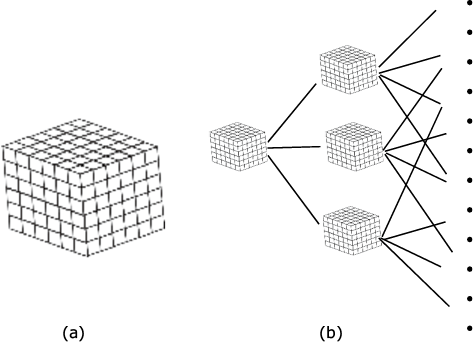
In estimating bedrock density distribution, a representation that expresses underground bedrock as an aggregation of cubes (voxels) is shown in Fig. 5 (a). By expanding this into multilayers as shown in Fig. 5 (b), it is possible to reconstruct an arbitrary density distribution.
In an ill-posed problem, the accuracy of the solution can be increased when there is more prior information available. By defining the error function as formula (A), it is possible to add prior information other than the shape and size of the detection target. Thus, the formulation shown in formula (A) can be used generically in various muography applications.
5. Applications of Muography
Validation of the effectiveness of muography is already underway in geoscience including volcano monitoring and tide-level monitoring. NEC installed the Tokyo Bay Seafloor Hyper Kilometric Submarine Deep Detector (TS-HKMSDD) ― the first of its kind in the world ― in collaboration with the International Muography Cooperative Research Organization at the University of Tokyo. This system successfully conducted real-time measurements of astronomical tide levels in Tokyo Bay. NEC is also working on a muography system to monitor soil moisture levels to estimate the degree of danger of mudflows. Through these monitoring activities, we hope that we will be able to provide information regarding disaster prevention of tsunami, mudflows, and so on. We are also striving to develop practical applications for muography in other fields such as industrial infrastructure (blast furnaces, electric furnaces, power plants, etc.) and cultural heritage (pyramids, buried structures, etc.).
6. Conclusion
In this paper, we have introduced our challenges for developments using muography. Going forward, NEC is committed to enhancing public safety and security by bringing the observational power of muography to crucial social infrastructure monitoring.
Reference
- 1)TANAKA Hiroyuki: Muography: Key to Unlock the Secrets of the Pyramids in the 21st Century, 2017
- 2)Dezső Varga et al.:Cosmic muon detector using proportional chambers, European Journal of Physics, Vol.36 No.6 2015
Authors’ Profiles
MIYAMOTO Shinichi
Senior Expert
Safer City Solutions Division
Senior Expert
Safer City Solutions Division
MIYAZAWA Kazuhiro
Public Products Division
NEC Platforms
Public Products Division
NEC Platforms
TAKENO Toru
Assistant Manager
1st Government and Public Solutions Division
Assistant Manager
1st Government and Public Solutions Division
ISHIZAWA Yoshio
Assistant Manager
AI Analytics Division
Assistant Manager
AI Analytics Division
ASAMI Ryuta
AI Analytics Division
AI Analytics Division