
Global Site
Breadcrumb navigation
Key Functions
EMIStream and EMC Expert Option
EMIStream allows engineers who have little knowledge about EMI to filter possible EMI problems at the PCB design phase and fix them by following advice from EMIStream. Thresholds and parameters are set with efficient default values through product development experience and research results obtained by NEC Laboratory in collaboration with various universities.
EMC Expert Option is add-on option of EMIStream. This option, which is available for professionals, enables your EMC engineers or consultants to customize in-depth thresholds and parameters to provide a more accurate analysis result.
In addition, it enables you to transfer the settings from EMC Expert Option into EMIStream. This makes it easier to share the knowledge of your EMC engineers with fellow engineers or outsourcing design bureaus.
EMIStream Key Functions
1. EMI Design Rule Check
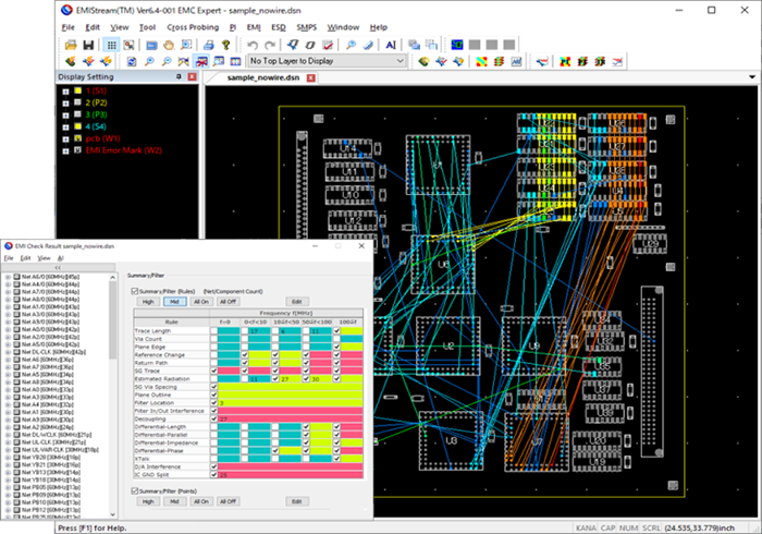
This function provides advice related to scanned components, traces, and plane location.
EMIStream's 15 rule check items are boiled down from a huge amount of historical know-how about EMI suppression countermeasures and have been verified by NEC Laboratory and local and overseas university researchers with a logical background.
In this way, EMIStream utilizes the most valuable items for real-world PCB design.
15 Rule Check Items
Return Current Path Discontinuity Check
-
Reference Change
-
Return Current Path Discontinuity
-
Traces Near Plane Edge
-
SG Trace
-
SG Via Spacing
Power Plane Check
-
Grounding Vias Along Plane Outline
-
Decoupling Capacitor
-
Digital/Analog Interference Check
-
IC Ground Split Check
Trace Check
-
Trace Length
-
Via Count
-
Estimated Radiation
-
Filter
-
Differential Signal
-
XTalk
Narrowing EMI check results down using AI
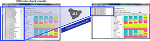
You can narrow EMI check results down to significant errors using an AI that has learned EMC Experts' know-how of design review.
This function allows you to shorten the review time, and suppress variations in design quality.
Cross Probing between EMI Check and Schematic
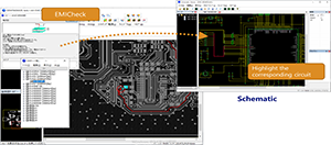
You can bi-directionally search for and highlight data by linking EMI check results with the schematic (nets, parts, and pins).
You can establish this linkage by displaying the schematic diagram in the Schematic Viewer after conducting an EMI check. When you select an EMI check result error, the corresponding circuit is highlighted in the Schematic Viewer.
EMI Check Batch Execution Function
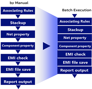
You can execute EMI checks from the command line.
By executing EMI checks from the command line, you can execute a series of EMI check operations in batch as shown in the right flowchart.
Error Filtering Function
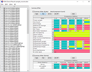
This function allows you to filter errors and hone in on critical problems relevant to your design. The Design Rule list lets you look at certain rules of your choice as well as narrow down the frequency range (of the nets). The Error Point list is organized by number of error points, which also gives you the frequency range columns. You can customize the frequency and error point ranges.
EMI Check Report Function
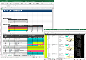
You can export EMI Check results in an Excel format. It displays the error, the location on PCB, and advice on how to fix the problem. This is very useful when sharing results with fellow engineers or an outsourcing design bureau.
You can edit comments and customize the report to fit your needs.
Estimated Radiation Value Graph Display
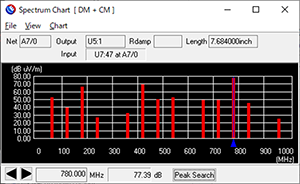
The frequency spectrum chart display of estimated radiated electromagnetic field allows you to see the problematic frequency range at a glance. The Expert Option lets you to set the IC rise time and damping/termination resistor value for individual nets and override the global value that is set in the parameter. By putting in specific parameters for nets, you can get more accurate results.
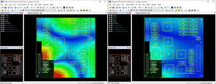
2. Power/ Ground Resonance Analysis
EMI increases if resonance occurs between the power/ground. The Power/ Ground Resonance Analysis Function takes into account plane shapes, capacitors, and distance between the power/ground planes to analyze resonance based on the PEEC (Partial Element Equivalent Circuit) method.
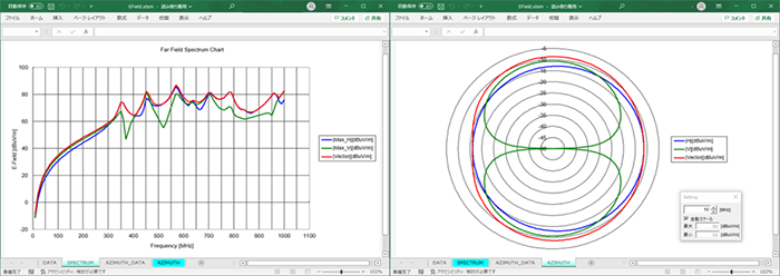
Far Field EMI Calculation
Far Field EMI is calculated by plane edge voltage (one pair of ground and power). It displays far field horizontal/vertical frequency characteristics and an azimuth pattern. You can adjust the calculation environment, such as the position of the PCB on the turntable, the distance to the antenna, and the antenna height.
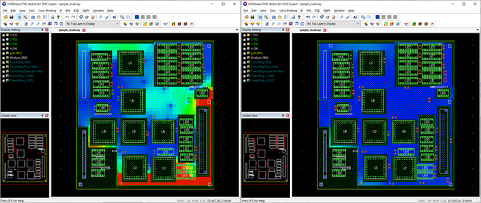
Multi-layer Resonance Analysis
You can analyze multiple layers at a time. It is possible to reduce resonance by changing capacitor placement, and now EMIStream allows you to take via placement into account and change/add locations as needed.
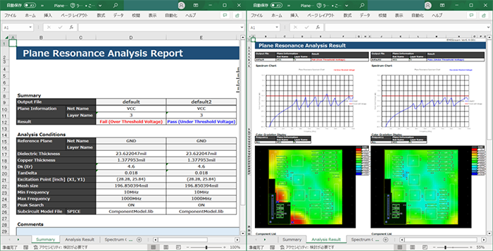
Resonance Analysis Report
Resonance analysis results such as analysis conditions, spectrum chart and voltage-distribution color gradation maps are reported collectively in an Excel format.
Two or more analysis results, such as results of before / after adding capacitors or analysis results of all power planes on boards, can be reported collectively. These Reports can be preserved as evidence.
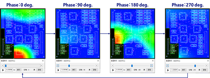
Movie Feature of Resonance Analysis Results
You can display resonance analysis results as a video. By displaying resonance analysis results in the time domain, you can visually understand changes in voltage distribution.
In addition, when resonance occurs, you can see if two hot spots are in phase or if their phases are opposite each other.
Contact