Antenna heat dissipation technology that enables miniaturization of wireless units for 5G
Featured Technologies
September 20, 2018
Background
With the recent significant growth in mobile traffic, there are rising expectations for the early realization of 5G mobile networks, which are forecast to have a larger capacity than current 4G mobile networks, along with capabilities such as ultra-high speed and ultra-low latency. NEC is aiming to achieve large-capacity communications by incorporating massive-element antennas into wireless units at mobile phone base stations, and by utilizing beam-forming with massive-element antennas. However, in wireless units for 5G small cell systems that use massive-element antennas, a large amount of heat is generated due to the increased power consumption associated with the greater number of analog devices. For this reason, heat sinks with a larger volume are required to dissipate the heat, which increases the size of wireless units and poses restrictions on where they can be installed. NEC's newly developed antenna heat dissipation technology achieves a reduction in heat sink volume by increasing the heat dissipation performance, and makes it possible to miniaturize wireless units with the use of a natural cooling method.
Features of the new technology
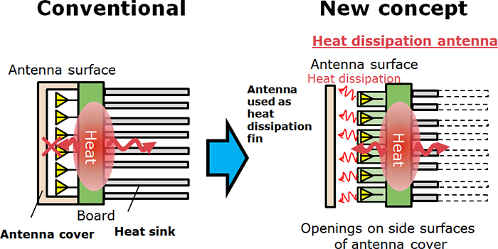
In conventional wireless units, the heat generated by circuits and other components is dissipated by a heat sink on the rear surface of the antenna, and not by the antenna surface itself. NEC's antenna heat dissipation technology is based on a new concept of dissipating heat from the antenna surface, which previously was not designed to dissipate heat (Figure 1). The heat dissipation efficiency is improved by dissipating heat from the surfaces of both the antenna and the heat sink, which makes it possible to reduce the size of heat sinks and miniaturize wireless units.
Figure 1: Concept of heat dissipation antenna
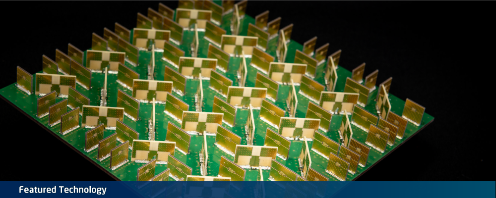
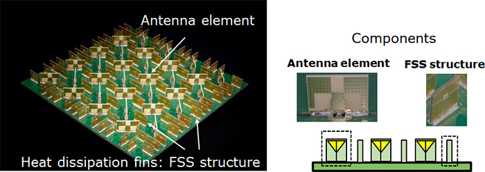
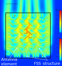
Addition of heat dissipation function to antennas, which conventionally do not have this function On the surface of a massive-element antenna that incorporates the new technology, the antenna elements function as heat dissipation fins, and many additional metal plates that function as heat dissipation fins are arranged between and around the antenna elements, thereby improving the heat dissipation effect (Figure 2). Figure 2: Massive-element antenna array The heat dissipation effect of the antenna is improved by expanding the metallic surface area of the antenna elements, which increases the share of the total area that is composed of metal. Furthermore, the additional metal plates employ a frequency-selective surface (FSS) structure, making them electromagnetically transparent to specific radio wave frequencies. This allows specific radio wave frequencies to pass through the plates without any reflection, even though the plates consist of metal. As a result, the addition of heat dissipation fins increases the efficiency of heat dissipation without disrupting the radio waves of the antenna. This antenna technology makes it possible to dissipate heat from both the antenna and the heat sink, while maintaining the radio emission properties (Figure 3). Without heat dissipation fins (antenna element only)Heat dissipation fins: Without FSS structure
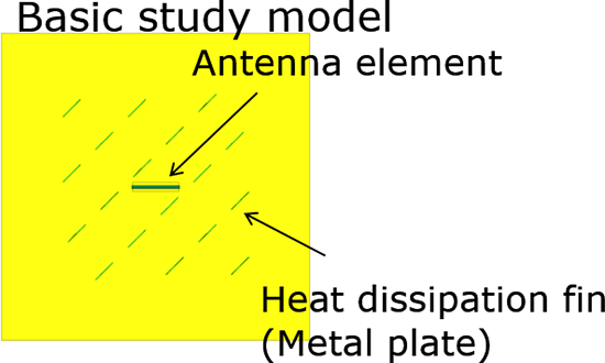
Heat dissipation fins with FSS structure allow radio waves to pass through, so that there is no interference with the antenna emissions.
Figure 3: Image of radio wave transmission through metal plates with FSS structure
Securing an air flow path that increases heat dissipation efficiency The heat dissipation from the antenna surface cannot be performed efficiently only by adding heat dissipation functions to the antenna elements. It is important to secure an air flow path between the antenna elements, so that the air containing the heat transferred by the antenna elements can flow through. This heat dissipation technology incorporates antennas with a split-ring structure (Note 1), which enable the antenna size to be reduced to approximately half that of ordinary patch antennas, thereby expanding the amount of space available between antenna elements. In addition, the antenna elements are oriented vertically and arranged in a "checker plate" style pattern, which produces polarized radio waves that bisect each other at right angles, while also ensuring a flow path for the air that contains the heat. By arranging the additional metal plates with FSS structure on the antenna surface so that they do not block the air flow path, heat dissipation from the antenna surface is achieved (Figure 4). In this manner, by increasing the density of the heat dissipation fins and securing a proper air flow path, the heat dissipation efficiency is increased while maintaining the antenna communication properties. Figure 4: Image of heat dissipation
In the simulation of the wireless communication unit, the assumed configuration consists of one circuit board, an antenna array on the front surface of the unit, and a heat sink on the rear surface. There are openings on the side surfaces of the antenna cover. The assumed heat source is a 35W multi-chip module on the rear surface of the circuit board, and the assumed wind speed is 1 m/s.
※
The information posted on this page is the information at the time of publication.